Gearbox - mechanical, two-shaft, with five forward gears
It is structurally combined with the differential and final drive.
The gearbox housing consists of three parts: clutch housing 25, gearbox housing 7 and rear cover of the gearbox housing 1.
During assembly, a gas-oil-resistant sealant is applied between them - a gasket.
In the clutch housing socket there is a special magnet that holds metal wear debris.
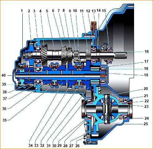
Gearbox: 1 – rear cover of the gearbox housing; 2 – drive gear of 5th gear; 3 – ball bearing of the input shaft; 4 – drive gear of the 4th gear of the input shaft; 5 – input shaft; 6 – drive gear of the third gear of the input shaft; 7 – gearbox housing; 8 – drive gear of the 2nd gear of the input shaft; 9 – reverse gear; 10 – reverse intermediate gear; 11 – drive gear of the first gear of the input shaft; 12 – roller bearing of the input shaft; 13 – breather; 14 – input shaft oil seal; 15 – clutch release bearing; 16 – clutch release bearing guide sleeve; 17 – main gear drive gear; 18 – roller bearing of the secondary shaft; 19 – oil sump; 20 – satellite axis; 21 – speed sensor master ring; 22 – axle gear; 23 – differential box; 24 – satellite; 25 – clutch housing; 26 – drain plug; 27 – driven gear of the main gear; 28 – adjusting ring; 29 – tapered roller bearing of the differential; 30 – axle shaft seal; 31 – driven gear of the 1st gear of the secondary shaft; 32 – synchronizer of 1st and 2nd gears; 33 – driven gear of the second gear of the secondary shaft; 34 – driven gear of the third gear of the secondary shaft; 35 – synchronizer for 3rd and 4th gears; 36 – driven gear of the fourth gear of the secondary shaft; 37 – ball bearing of the secondary shaft; 38 – driven gear V of the secondary shaft transmission; 39 – 5th gear synchronizer; 40 – secondary shaft
Input shaft 5 is designed as a block of drive gears, which are in constant engagement with the driven gears of all forward gears.
Secondary shaft 40 is hollow (to supply oil under the driven gears), up to the removable drive gear of the main gear 17.
It contains driven gears 31, 33, 34, 36, 38 and synchronizers 32, 35, 39 for forward gears.
The front bearings of shafts 18 and 12 are roller, the rear bearings 3 and 37 are ball.
Radial clearance in roller bearings should not exceed 0.04 mm.
Under the front bearing 18 of the secondary shaft there is an oil sump 19 that directs the flow of oil into the shaft.
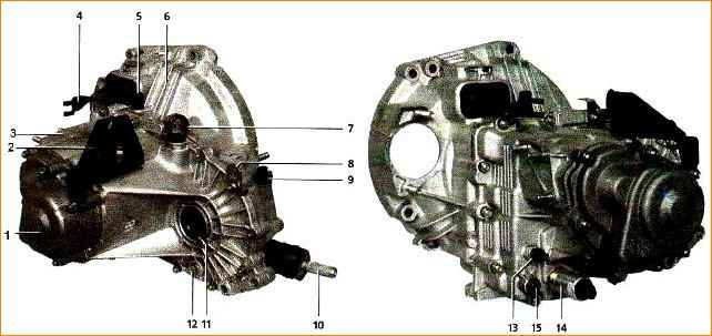
External view of the gearbox: 1 - rear cover of the gearbox housing; 2 - bracket for the clutch release cable; 3 - gearbox housing; 4 - clutch release fork lever; 5 - breather; 6 - clutch housing; 7- level indicator (dipstick); 8 - eye; 9 - speed sensor; 10 - shank of the gear selector rod hinge; 11 - left wheel drive oil seal; 12 - drain plug; 13 - reverse light switch; 14 - reverse gear lock solenoid; 15 - reverse gear fork clamp plug
Differential - two-satellite.
Preload in bearings 29 (0.25 mm) is adjusted by selecting the thickness of ring 28, installed in the gearbox housing housing under the outer ring of the differential bearing. The driven gear of the main gear 27 is attached to the differential box flange.
The gearbox communicates with the atmosphere through breather 14 located in its upper part.
The gearbox control drive consists of a gear shift lever, a ball joint, a control rod, a gear selector rod and a gear shift mechanism.
To prevent the gears from switching off spontaneously due to the axial movement of the power unit when the vehicle is moving, a reaction rod is introduced into the gearbox control drive, one end of which is connected to the power unit, and the other end is attached to the base of the gear shift lever.
A switch (lever) is attached to the inner end of the rod, which acts on the three-arm lever of the gear shift mechanism.
This mechanism is made as a separate unit and is attached to the clutch housing.
The gear shift housing has three axes.
One has a three-arm gear selection and engagement lever and two locking brackets.
The other axis passes through the holes of the locking brackets, fixing them from the turning.
The gear selector, mounted on the rod, acts on the arm of the gear selection lever, which in turn engages forward gears with one arm, and reverse gear with the other.
A reverse gear fork is installed on a separate axle.
To prevent accidental engagement of reverse gear, a reverse gear lock solenoid is installed in the gearbox.
The protruding part of the solenoid core prevents the locking brackets from moving along the axes until the reverse gear is engaged.
The solenoid switch is installed on the gear shift lever.
When the ring under the handle is raised, the switch contacts close and voltage is applied to the solenoid.
The solenoid core retracts and makes it possible to engage reverse gear.
If the solenoid fails or its electrical circuit is broken, it becomes impossible to engage reverse gear.
In order to engage reverse gear and drive to a garage or service station, where the fault can be repaired, you should unscrew the solenoid from the gearbox housing and in its place screw in the shift fork rod lock plug, which we recommend taking with you.
At the same time, while driving the car, you should be careful not to accidentally engage reverse gear instead of first.
After eliminating the malfunction, add oil to the gearbox, since some of it will leak out when the solenoid is turned out.
The gearbox is filled with transmission oil at the factory, designed for 75,000 km.
The oil level should be between the control marks on the oil level indicator.
Tightening torques for gearbox threaded connections
Name of components and parts – Thread - Tightening torque, Nm (kgf.m)
- Drain plug M22x1.5 - 28.7-46.3 (2.9-47)
- Reverse light switch M14x1.5 - 28.4-45.3 (259-4.6)
- Nut securing the speed sensor drive housing M6 - 4.5-7.2 (11.7-18.6)
- Nuts securing the gearbox to the clutch housing M8 - 15.7-25.5 (1.6-2.6)
- Bolt with the conical part of the gear shift drive rod joint M8 - 16.3-20.1 (1.7-2.1)
- M8 gear lever housing mounting bolts - 15.7-25.5 (1.6-2.6)
- M6 gear shift mechanism mounting bolts - 6.4-10.3 (0.7-1.1)
- Nuts of the gear shift drive rod clamps M8 - 15.7-25.5 (1.6-2.6)
- Gear shift lever limiter mounting bolt M6 - 11.7-18.6(1.2-1.9)
- Mount torque bracket mounting bolts M8 - 14.0-32.0 (1.4-3.2)
- Reverse fork clamp plug M16x1.5 - 28.4-35.0 (2.8-3.6)
Possible gearbox malfunctions and methods of elimination
Cause of malfunction - Elimination methods
Noise in the gearbox (The noise decreases or disappears when the clutch is depressed)
Insufficient oil level in the gearbox housing - Check the level, add oil if necessary. Check for leaks. Blow out the breather
Poor oil quality. Water has gotten into the oil (when water gets into the oil, a white emulsion is formed, which can be seen on the dipstick) - Change the oil. Cross fords and deep puddles carefully.
Install the engine splash guard, put the tube on the gearbox breather and lead it up to a place protected from splashes
Wear or damage to bearings and gear teeth - Replace worn bearings and gears
Gears are switched on with difficulty, there is no extraneous noise
The gearshift drive rod is deformed - Straighten or replace the rod
The bolts securing the hinge or gear selector lever are loose - Tighten the bolts (apply anaerobic sealant to their threaded part)
Failure of plastic parts of the control drive - Replace parts
Incorrect drive adjustment - Adjust drive
The springs of the gear shift mechanism are broken, its parts are deformed - Replace the springs, straighten the deformed parts or replace the mechanism assembly
Loose fit of the gearshift forks on the rods - Tighten the fork clamps on the rods
Gearbox shaft nuts are not tightened - Tighten the nuts
Clutch does not disengage completely - See fault “Clutch is moving”
Gears turn off spontaneously
Damage or wear of the splines on the clutch, gear or synchronizer hub - Replace defective parts
Incorrect drive adjustment - Adjust drive
The springs in the gear shift mechanism are weakened, the rods are worn - Replace the worn parts
Gearbox shaft nuts are not tightened - Tighten the nuts
The power unit supports have lost their elasticity or have collapsed - Replace the supports
Noise, crackling, squealing of gears when the gear is engaged
Clutch does not disengage completely - See fault diagnosis clutch correctness
There is no oil in the gearbox housing - Add oil. Check for leaks. Blow out the breather
Damaged bearings, gear teeth - Replace bearings, gears
Wear of the gear shift synchronizer ring - Replace the ring
Final drive noise (Noise from the gearbox side only when the vehicle is moving)
Worn or damaged bearings - Replace damaged and worn secondary shaft and differential bearings (even with minimal wear). Adjust the preload of the differential box bearings
Reverse gear does not engage
The solenoid is faulty - Replace the solenoid or remove it and plug the hole in the gearbox
The solenoid activation circuit is faulty - You can supply power to the solenoid directly from the battery
Oil leak
Wear of seals: input shaft, drives, gear selector rod, wear of speed sensor seal - Replace seals. Blow out the gearbox breather
Extreme wear, nicks on the surface of the shafts on which the oil seals operate - Clean minor damage with fine-grained sandpaper and polish.
When installing a new oil seal, you can slightly underpress it so that the edge of the oil seal works along the unworn part of the shaft (in this case, to avoid distortion, you can place spacers up to 1 mm thick under the oil seal). In case of significant damage, replace the shafts and seals
Large play in the transmission input shaft - Check the condition of the shaft bearings, their seating surfaces, and the tightness of the nut. Replace worn parts
The clutch housing and gearbox cover are loose - Tighten the threaded connections
Drain plug, reverse light switch, reverse lock solenoid, fork rod clamp plugs are not tightly screwed - Tighten the drain plug, light switch, solenoid, clamp plugs
Basic data for monitoring, adjustment and maintenance
Gearbox oil (API group) - GL-4 or GL-4/5
Recommended viscosity grade of gear oil according to SAE:
- -40 ˚C — +35 ˚C - 75W80, 75W85
- -40 ˚C — +45 ˚C - 75W90
- -26 ˚C — +35 ˚C - 80W85
- -26 ˚C — +45 ˚C - 80W90
Filling volume - 3.1 l
Dimensions of drive seals (right * 2110-2301034, 2110-2301034-01; left * - 2110-2301035, 2110-2301035-01), mm:
- Outer diameter 57
- Inner diameter 35
- Width 9
Dimensions of the input shaft oil seal (2110-1701043), mm:
- Outer diameter 45
- Inner diameter 25
- Width 9
Dimensions of gear selector rod oil seal (2108-1703042-01), mm:
- Outer diameter 30
- Inner diameter 16
- Width 7
* the oil seals of the left and right drives are not interchangeable, since they have different directions of the oil drainage grooves