The principle of operation of the system is simple: receiving data from the speed sensors of all wheels and from the vehicle speed sensor, the control unit controls the rotation of each wheel and, if the wheel locks during braking, reduces the pressure in the corresponding brake circuit
The ABS system ensures full control of the car during emergency braking, but does not lead to a reduction in braking distance.
Therefore, you need to maintain the correct distance.
On vehicles with an ABS system installed, a four-channel system is used.
The channels are connected in a diagonal pattern.
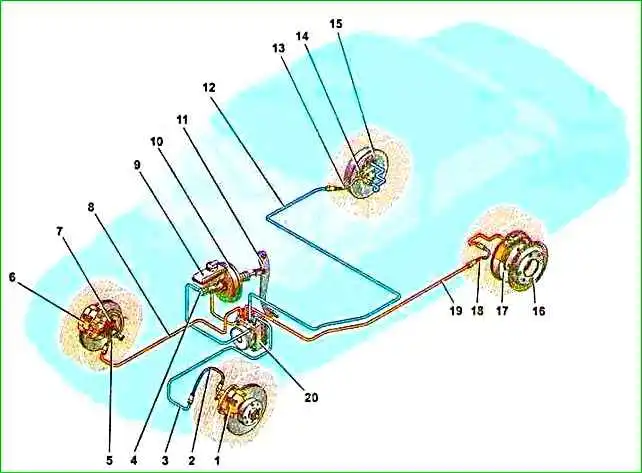
The executive element of the anti-lock braking system is a hydraulic modulator. This is a complex unit in which a hydraulic pump and solenoid valves are built in.
It is installed in the engine compartment.
The operation of the hydromodulator is controlled by an electronic unit installed on the hydromodulator.
The control unit also monitors the serviceability of all elements of the ABS system.
The front and rear brake mechanisms are equipped with wheel speed sensors.
Inductive type sensors
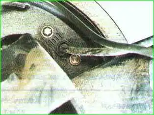
For the operation of sensors installed in the front brake mechanisms, gears are made on the housings of the external hinges of the front wheel drives.
To operate the sensors, master discs are installed in the rear mechanisms under the brake drums.
Pulse signals from the sensors enter the control unit.
When one of the wheels is blocked, the hydraulic modulator, at the command of the control unit, limits the pressure in the corresponding channel.
If a malfunction is detected, the control unit informs the driver using a warning lamp on the instrument panel.
You can determine the problem by fault codes.
ABS malfunction may be caused by a failure of the wheel rotation sensors or a malfunction of the hydraulic valve block itself.
If the ABS fails, the braking system remains operational, but braking efficiency is reduced.
Removing the ABS hydraulic unit
We install the car on a lift or inspection ditch.
Remove the battery.
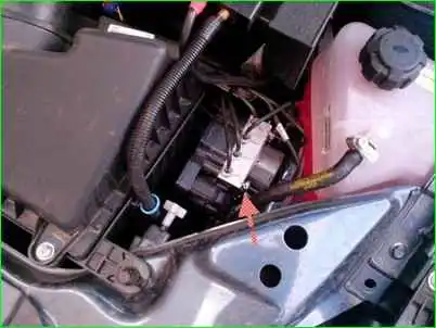
Disconnect the plug block of the wires from the hydraulic unit.
We disconnect the brake pipes going to the brake mechanisms from the hydraulic unit of the anti-lock braking system. We install plugs on the tubes and holes in the hydraulic unit.
Disconnect the pipes of the primary and secondary circuits of the master cylinder from the ABS hydraulic unit.
Using a 13mm socket, unscrew the two bolts securing the hydraulic unit bracket to the front side member.
Remove the hydraulic unit with the bracket assembly.
Use a 10mm wrench to unscrew the hydraulic unit from the bracket.
Installing a hydraulic unit
Install the hydraulic unit onto the bracket and secure it with nuts. The tightening torque of the nuts is 7 – 10 Nm.
Install the hydraulic unit with the bracket assembly onto the car body and tighten the two bolts and washers securing the hydraulic unit to the left side member.
Remove the plugs and attach the tubes to the ABS hydraulic unit. The tightening torque of the tube fittings is 15 – 18 Nm.
Attach the plug block. Install the battery. We bleed the brake system.
Removing and installing the front wheel ABS sensor and rotor
We install the car on a lift or inspection ditch.
Disconnect the front wheel speed sensor harness block from the front wiring harness.
Using a flat-head screwdriver, remove the speed sensor harness block holder from the hole in the car body.
Remove the sensor harness from the brackets on the front suspension strut and the car body.
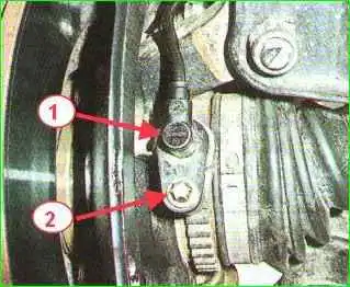
Using a TORX E8 socket, unscrew the bolt securing the speed sensor to the bracket on the steering knuckle and remove the sensor.
Installing the front wheel speed sensor
Before installation, apply AZMOL LSC-15 lubricant to the mating holes. Install the sensor in reverse order. The tightening torque of the sensor mounting bolt is 6 – 9 Nm (0.6 – 0.9 kgcm).
If it is necessary to replace the ABS rotor of the front wheel, then replace the drive assembly: (right front wheel drive part. 11180-2215010-10, left front wheel drive part. 21700-2215011-00) or the outer hinge assembly (part. 11186-2215012-00).
Removing the speed sensor and rear wheel rotor of the Lada Granta
We install the car on a lift or inspection hole.
Disconnect the rear wheel speed sensor harness connector from the wiring harness.
Using a flat-head screwdriver, remove the speed sensor harness block holder from the hole in the car body.
Remove the rear wheel speed sensor harness from the mounting brackets located on the rear suspension arms and vehicle body.
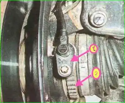
Use a TORX E8 socket to unscrew the bolt securing the speed sensor to the bracket.
Remove the rear wheel speed sensor.
Before installing the speed sensor, lubricate the mating parts with grease.
The tightening torque of the sensor mounting bolt is 6 – 9 Nm.
Removing the rear wheel rotor
Place the car on a lift and remove the rear wheel.
Unscrew the guide pins using a 7-head socket

Insert the pins into the threaded holes of the brake drum and screw the pins in sequence. Thus, compressing the brake drum.

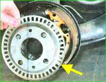
Remove the brake drum

Remove the rear wheel rotor
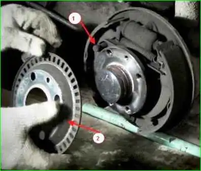
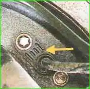
In the rear block of a car with an ABS system there is a hole into which the tip of the speed sensor fits
Installation
Apply grease to the hub seating belt, install the brake drum and tighten the guide pins.
Tightening torque of pins 7 – 15 Nm.
Install the wheel.
")

")
")
")
")
")
")
")