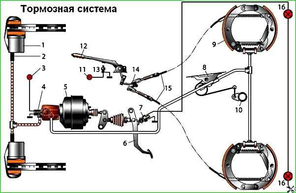
The car is equipped with a dual-circuit braking system
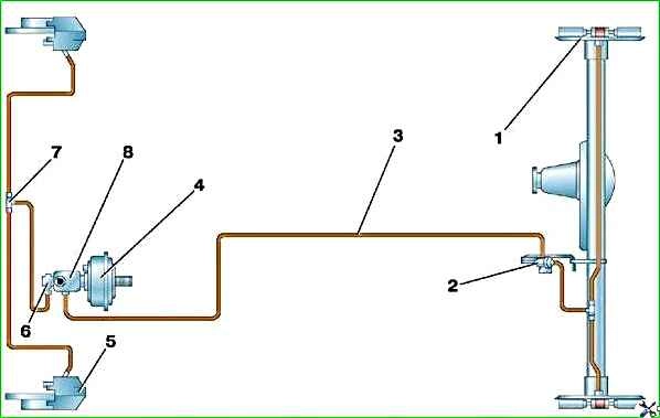
The diagram of the working brake system is shown in the figure
The system drive is hydraulic. To facilitate drive control, a vacuum booster is installed on the vehicle.
The front brakes are disc, and the rear are drum.
The front brake discs are ventilated. They are mounted on the hubs and secured with wheel bolts.
The floating brake caliper is secured with two bolts to the steering knuckle.
The front wheel brakes are disc, with a single-piston floating caliper (when braking, the piston presses the inner pad against the disc, and the caliper, moving in the opposite direction, presses the outer pad).
The minimum permissible thickness of the front brake pads when worn is 3 mm.
The disks are ventilated, mounted on the hubs and secured to them with wheel bolts.
The minimum permissible disc thickness when worn is 19 mm. The bracket is attached with two bolts to the steering knuckle.
The brake cylinder is made in the caliper body; on the outside it is covered with a rubber cover (boot) to protect it from dirt.
Inside the cylinder there is a groove into which an o-ring (cuff) is inserted.
When the piston moves out of the cylinder during braking, this ring twists slightly and after braking ends, it tends to return the piston to its original position.
Due to this, a constant minimum gap between the discs and brake pads is maintained. The cylinder has a bleed valve.
To protect the working surfaces of the disc, a brake shield is installed, which prevents the ingress of dirt and moisture, and also ensures cooling of the disc.
The rear wheel brakes are drum-type, with two-piston wheel cylinders with automatic adjustment of the gap between the shoes and the drum.
Thrust rings are inserted into the cylinder with interference, limiting the free movement of the pistons (after braking is completed), thereby maintaining a constant gap between the pads and the drum.
As the pads wear, the rings shift by the amount of wear. There are eccentrics in the lower hole of the brake pads for adjusting the position of the pads after replacing them.
The minimum permissible thickness of the rear brake pads when worn is 1 mm.
The maximum permissible internal diameter of the brake drum is 283 mm.
The rear brake pads are actuated by one double-acting wheel cylinder.
The connection of the thrust rings, inserted with tension into the cylinder, and the pistons acts as an automatic device that maintains a constant gap between the friction linings of the shoes as they wear out and the working surface of the drum when the rear brake is not blocked.
Adjusting eccentrics are inserted into the lower holes of the brake pads to set the brake pads in the correct position after replacement.
Due to the vacuum in the engine intake pipe, the vacuum booster during braking creates additional force on the piston pusher of the brake master cylinder in proportion to the force on the pedal.
The vacuum booster is connected to the intake pipe through a hose and a check valve, which maintains vacuum in the booster when the vacuum in the engine intake pipe drops.
The vacuum booster is located between the pedal assembly and the main brake cylinder and is attached to the bracket with four studs.
The amplifier is of a non-separable design; if it fails, it is replaced.
The simplest check of its serviceability is as follows: on a car with the engine turned off, press the brake pedal several times and, holding the pedal pressed, start the engine.
If the amplifier is working properly, after starting the engine the pedal should “move” forward.
Failure to operate or insufficient efficiency of the vacuum booster may be caused by a leak in the vacuum hose from the intake manifold.
An adjusting bolt with a lock nut is screwed into the front end of the booster pusher, providing the required clearance for proper operation of the brake master cylinder.
The tandem master cylinder has two separate compression chambers and creates pressure in two independent circuits of the front and rear brakes.
The first camera controls the rear brake cylinders, and the second controls the front brake cylinders.
The main brake cylinder is attached to the vacuum booster housing on two studs.
A translucent polyethylene brake reservoir with an insufficient fluid level sensor (in the reservoir cap) is inserted into the holes in the upper part of the cylinder.
In the front part of the cylinder (along the direction of the car) there is a plug screwed in, which serves as a stop for the return spring and is sealed with a copper gasket.
The pistons in the master cylinder are arranged in series, the one closest to the vacuum booster operates the rear brakes, the other piston operates the front brakes.
The rubber sealing rings (cuffs) of the main brake cylinder are asymmetrical in cross-section, so it is important to orient them correctly during assembly.
When disassembling the cylinder, it is recommended to replace the cuffs regardless of their condition.
When installing the master cylinder on a vehicle, check the gap (1.35–1.65 mm) between the end surface of the vacuum booster housing and the adjusting bolt.
If the gap value differs from the specified value, unscrew the lock nut and, by rotating the adjusting bolt, achieve the desired gap, then tighten the lock nut.
The master cylinder reservoir cavity is divided into two compartments, each of which feeds one of the master cylinder chambers.
The brake fluid level sensor is installed in the reservoir cap. The lamp that lights up from its signal indicates that the tightness of the brake system is broken.
The brake pressure regulator adjusts the brake fluid pressure in the wheel cylinders of the rear brakes, eliminating the possibility of the rear wheels locking before the front ones.
The regulator is mounted on the underbody and reacts to the load of the rear axle through a load spring.
The pressure regulator is attached with two bolts to a bracket in the rear of the body.
It prevents the rear wheels from locking earlier than the front wheels, which increases the vehicle's directional stability when braking.
Reacting through a load spring to the load on the rear axle, it limits the fluid pressure in the rear brake circuit.
The regulator cannot be repaired - if it fails, it must be replaced.
After replacing the adjuster or rear suspension components, it is necessary to readjust the position of the load spring relative to the rear axle.
Parking brake system drive – mechanical, cable, to the rear wheels.
It consists of a lever (with a handle and a locking mechanism), an intermediate lever and its rod, an equalizer and its rod, cables, a drive lever with a rod in the rear brake mechanisms.
The free play of the drive lever is adjusted by an eccentric on the rear block, and the tension of the cables is adjusted by an adjusting nut on the equalizer rod.
")

")
")
")
")
")
")
")