The engine is in-line four-cylinder, equipped with an integrated microprocessor fuel injection and ignition control system (KMSUD)
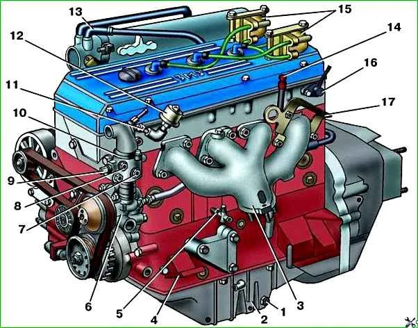
The cylinder block is cast from gray cast iron. Between the cylinders there are channels for coolant.
The cylinders are made without insert liners.
At the bottom of the block there are five supports for the crankshaft main bearings.
The main bearing caps are made of ductile iron and are attached to the block with two bolts.
The bearing caps are bored together with the block, so they cannot be swapped. All covers, except the cover of the third bearing, have their serial numbers stamped on them.
The third bearing cover together with the block is machined at the ends to install thrust bearing half washers.
The chain cover and oil seal holder with crankshaft seals are bolted to the ends of the block.
The oil sump is attached to the bottom of the block. On top of the block is a cylinder head cast from aluminum alloy.
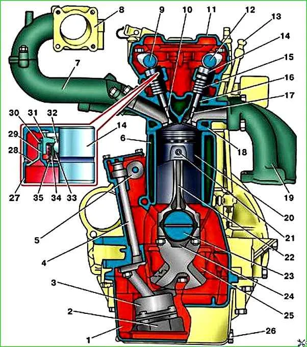
It contains inlet and outlet valves. Each cylinder has four valves, two intake and two exhaust.
Intake valves are located on the right side of the head, and exhaust valves are located on the left.
The valves are driven by two camshafts through hydraulic pushers.
The use of hydraulic pushers eliminates the need to adjust the gaps in the valve drive, since they automatically compensate for the gap between the camshaft cams and valve stems.
On the outside of the hydraulic pusher body there is a groove and a hole for supplying oil into the hydraulic pusher from the oil line.
The piston rests against the bottom of the hydraulic pusher housing.
The hydraulic pusher has a steel body, inside of which a guide sleeve is welded.
A compensator with a piston is installed in the bushing. The compensator is held in the bushing by a retaining ring.
An expansion spring is installed between the compensator and the piston, which presses the body of the check ball valve.
When the camshaft cam does not press on the hydraulic tappet, the spring presses the hydraulic tappet housing through the piston against the cylindrical part of the camshaft cam, and the compensator against the valve stem, thereby selecting clearances in the valve drive.
The ball valve is open in this position and oil flows into the hydraulic tappet.
Once the camshaft cam rotates and presses against the tappet body, the body will move down and the ball valve will close.
The oil located between the piston and the compensator begins to work as a solid.
The hydraulic tappet moves downward under the action of the camshaft cam and opens the valve. When the cam, turning, stops pressing on the hydraulic pusher body, it moves upward under the action of a spring, opening the ball valve, and the whole cycle repeats again.
Valve seats and valve guides are installed in the cylinder head with high interference.
The combustion chambers are located in the lower part of the block head, and the camshaft supports are located in the upper part. Aluminum covers are installed on the supports.
The front cover is common to the intake and exhaust camshaft supports.
This cover has plastic thrust flanges that fit into the grooves on the camshaft journals.
The covers are bored together with the block head, so they cannot be swapped. All covers, except the front one, have serial numbers stamped on them. The camshafts are cast from cast iron. The cam profiles of the intake and exhaust shafts are the same.
The cams are offset by 1.0 mm relative to the axis of the hydraulic pushers, which causes them to rotate when the engine is running. This reduces wear on the surface of the hydraulic pusher and makes it uniform.
The top of the block head is closed with a lid cast from aluminum alloy.
The pistons are also cast from aluminum alloy.
On the bottom of the piston there are four recesses for the valves, which prevent the piston from hitting the valves when the valve timing is disrupted.
For proper installation of the piston into the cylinder, the inscription “Front” is cast on the side wall of the boss under the piston pin: “Front.”
The piston is installed in the cylinder so that this inscription is upward, towards the bottom of the piston.
The oil scraper ring consists of three elements: two facing the front of the engine.
Each piston is equipped with two compression rings and one oil scraper ring.
Compression rings are cast from cast iron.
The barrel-shaped working surface of the upper ring is coated with a layer of porous chrome, which improves the running-in of the ring.
The working surface of the lower ring is covered with a layer of tin.
There is a groove on the inner surface of the lower ring. The ring must be installed on the piston by this groove of the steel discs and the expander.
The piston is attached to the connecting rod using a “floating type” piston pin, i.e. the pin is not secured in either the piston or connecting rod.
The pin is kept from moving by two spring retaining rings, which are installed in the grooves of the piston bosses.
Forged steel connecting rods, with an I-section rod.
A bronze bushing is pressed into the upper head of the connecting rod. The lower head of the connecting rod with a cover, which is secured with two bolts.
The nuts of the connecting rod bolts have self-locking threads and therefore are not additionally locked.
The connecting rod caps are processed together with the connecting rod and therefore cannot be moved from one connecting rod to another.
Cylinder numbers are stamped on the connecting rods and connecting rod caps.
To cool the piston bottom with oil, holes are made in the connecting rod rod and the upper head.
The mass of pistons assembled with connecting rods should not differ by more than 10 g for different cylinders.
Thin-walled connecting rod bearings are installed in the lower head of the connecting rod.
The crankshaft is cast from high-strength cast iron.
The shaft has eight counterweights. It is kept from axial movement by thrust half-washers installed on the middle neck.
A flywheel is attached to the rear end of the crankshaft.
A spacer sleeve and a gearbox input shaft bearing are inserted into the hole in the flywheel.
Cylinder numbers are stamped on the connecting rods and connecting rod caps.
To cool the piston bottom with oil, holes are made in the connecting rod rod and the upper head.
The mass of pistons assembled with connecting rods should not differ by more than 10 g for different cylinders.
Thin-walled connecting rod bearings are installed in the lower head of the connecting rod.
")

")
")
")
")
")
")
")