Disconnect the wire from the negative terminal of the battery
Disconnect the wire connector for sensor 3 located behind the engine intake pipe
Unscrew bolt 2 and remove sensor 1.
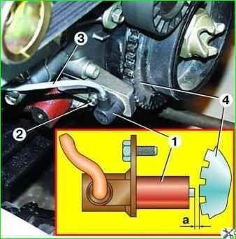
Check the resistance of the sensor coil with an ohmmeter, it should be in the range of 850-900 Ohms.
If the resistance value does not fall within the specified limits, replace the sensor.
Install the sensor in reverse order.
For normal operation of the sensor, the gap “a” between sensor 1 and synchronization disk 4 must be within 1.0-1.5 m
Checking the timing sensor
Turn off the ignition and disconnect the negative terminal of the battery.
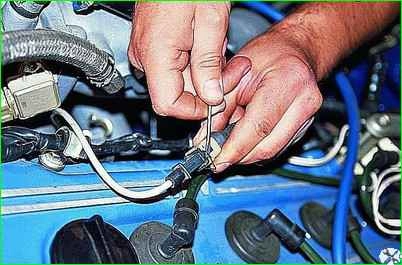
Use a thin screwdriver or awl to remove the spring clamp of the block.
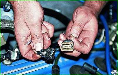
Disconnect the synchronization sensor connector.
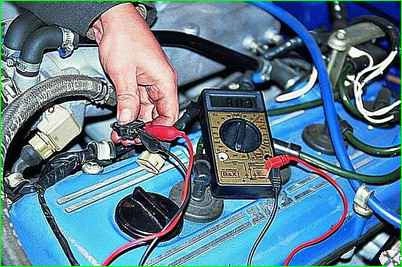
Connect an ohmmeter to the central and one side terminal.
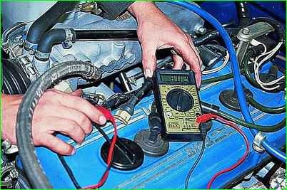
We measure the resistance of the sensor winding, which should be in the range of 700-900 Ohms.
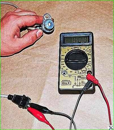
To further check the serviceability of the sensor, remove it from the engine.
You can verify that the sensor is working by connecting a voltmeter to its terminals.
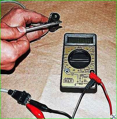
We quickly bring the metal rod to the sensor core - if it is working properly, voltage surges are observed on the device.
We replace the faulty sensor.
Removing the timing sensor
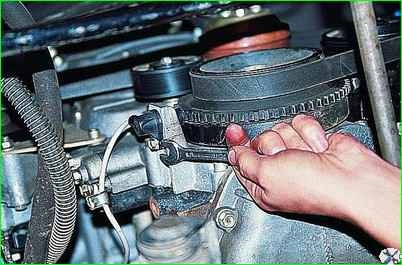
Use a 10mm wrench to unscrew the bolt securing the sensor to the engine block.
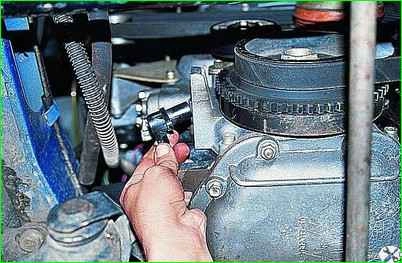
Remove the sensor from the hole.
Bending the sensor wire fastening clamps located on the intake manifold and cylinder block, pull the wire together with the connector down.
Install the sensor in reverse order.
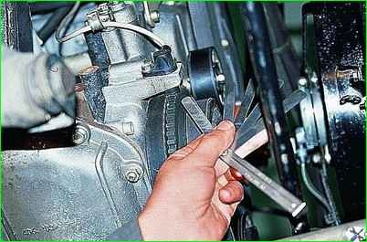
After installing the sensor, use a set of feeler gauges to check the gap between its rod and the teeth of the synchronization disk.
The gap should be within 1-1.5 mm.


