Mass air flow sensor – thermopneumatic flow meter IVKSH 407282000, installed in the intake system after the air filter.
The sensor determines the amount of air entering the cylinders during engine operation.
A platinum thread is stretched inside the sensor body. During operation, it heats up to a temperature of 150°C.
The air flow passing through the sensor body takes away more heat from it, the higher the air flow rate.
Based on the amount of electrical power expended to maintain the set filament temperature, the electronic unit calculates the mass flow of incoming air.
Since the cooling of the filament is affected by the temperature of the air itself, a thermistor is installed in the sensor housing, which changes its resistance in accordance with the temperature of the air flow entering the system.
Based on its readings, the electronic unit makes adjustments to the operation of the filament heating electrical circuit, thereby compensating for temperature changes caused by changing weather conditions.
The control system informs the driver about the occurrence of a malfunction in the mass air flow sensor circuit by turning on the KMSUD indicator lamp, the fault codes are entered into the memory of the electronic unit, and the engine will be switched to standby mode.
- Disconnect the wire from the negative terminal of the battery.
- Disconnect block 1 from mass air flow sensor 3. Loosen the clamps, disconnect the air supply hoses 2 and remove the sensor 3.
Install the new sensor in reverse order.

Checking the mass flow sensor
- Remove the mass air flow sensor.
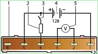
- Connect a voltmeter to contacts “2” and “3” of the sensor connector.
Apply 12 V direct current to contacts “1” and “5” (“+” to contact “5”, and “–” to “1”). In this case, the voltmeter should show a voltage of 1.3–1.4 V.
Then briefly close contacts “4” and “5” with each other. The voltmeter should show a voltage of about 8 V, and the platinum thread should become red-hot.
If at least one of these conditions is not met, replace the sensor.
Let's take a closer look at removing and checking the mass air flow sensor
Electrical circuit for checking the mass air flow sensor
Turn off the ignition and remove the negative terminal from the battery.

Pry the spring clamp of the block with an awl and disconnect the sensor connector.

Use a screwdriver to loosen the screws of the clamps, remove the clamps and remove the mass air flow sensor from the air ducts.


Checking the air flow sensor

We put short pieces of thin polyvinyl chloride tube on the pins of the electrical connector, inserting the ends of the wires exposed by 7-8 mm into them, and assemble the circuit shown in the figure.

When connecting the wires to the sensor, you need to follow the profile of the end of the connector.

We connect the wires to the battery last, making sure that the circuit is assembled correctly.

We take voltmeter readings with the device switch turned off.

For a working sensor, the voltage at pins 2 and 3 should be 1.3–1.4 V.

Turn on the switch for a short time and take voltmeter readings.
For a working sensor, the voltage at pins 2 and 3 should increase to approximately 8 V.
The platinum thread heats up red hot.
The faulty sensor must be replaced.
Install the mass air flow sensor in reverse order.
")

")
")
")
")
")
")
")