The crankshaft is cast from high-strength cast iron, five-bearing, has eight counterweights for better unloading of the supports.
Wear resistance of the main, connecting rod journals and the surface of the rear flange under the cuff is ensured by hardening with high frequency currents.
The fillets of the main and connecting rod journals of the shaft are rolled with rollers to strengthen them. The shaft is dynamically balanced.
Removal and disassembly of the crankshaft can be found in the article - Crankshaft ZMZ-4062 for GAZ-2705
The subassembly of the connecting rod and piston group can be found in the article - How to assemble the connecting rod and piston group of the ZMZ-40524 engine
Through holes are drilled in the main (except for the middle) and connecting rod journals, which are connected by oblique drillings passing through the journals and shaft cheeks; these channels serve to supply oil to the connecting rod bearings.
At the point where the drillings exit in the cheeks there are special dirt-collecting cavities closed with screw plugs.
During the rotation of the crankshaft, dirt contained in the oil is separated due to the action of the centrifugal force of inertia and accumulates in these cavities. In addition to the filter, additional oil cleaning occurs.
When carrying out engine repairs, it is necessary to remove the plugs and clean the dirt-collecting cavities and oil channels of the crankshaft from dirt and deposits.
The screw plugs are installed with Stopor-9 anaerobic sealant to prevent them from loosening themselves.
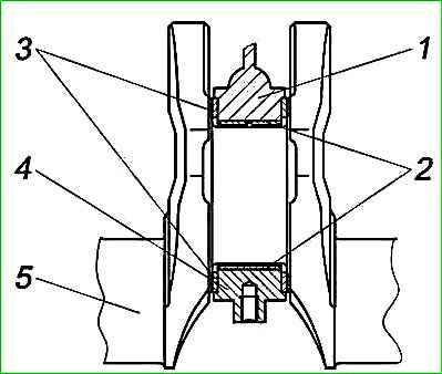
The axial movement of the shaft is limited by two washers 3 (Figure 1), located on both sides of the middle (third) main bearing.
Each of the thrust washers consists of two half-washers: upper and lower.
The direction of rotation of the crankshaft is right (when viewed from the side of the damper pulley).
At the front end of the crankshaft there are installed: drive sprocket 7 for camshaft drive, bushing 6 and pulley - damper 3 with a toothed synchronization disk, which are secured with a coupling bolt 1.
To prevent self-loosening of the coupling bolt, a toothed heat-strengthened washer 15 is used.
The outer surface of the steel bushing 6 is hardened with high frequency currents to increase wear resistance.
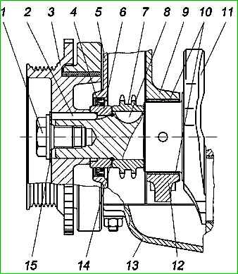
The front end of the crankshaft is sealed with a reinforced single-lip rubber cuff with a spring and boot, as well as a rubber ring 14 (Figure 2), installed between the spacer sleeve and the sprocket.
The crankshaft damper pulley has a special elastic rubber element that serves to dampen torsional vibrations of the crankshaft, thereby reducing noise and facilitating the operating conditions of the chain drive of camshafts.
The damper pulley is subjected to static balancing.
The toothed rim of the damper pulley serves to supply pulses to the synchronization sensor, with the help of which the microprocessor unit of the control system determines the crankshaft speed and the position of the crankshaft relative to TDC.
There is a mark on the damper disk, by the coincidence of which with the protrusion on the chain cover, the location of the piston of the first cylinder at TDC is determined.
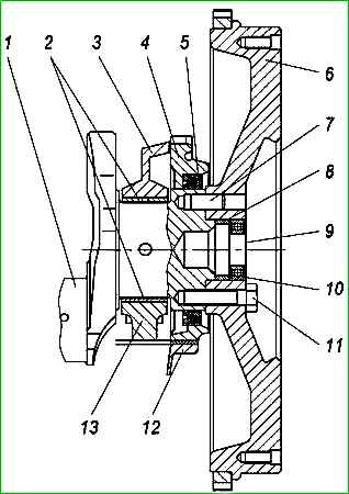
On the cylindrical protrusion of the rear end of the crankshaft (Figure 3) and pin 7, pressed into the rear flange of the crankshaft, a flywheel 6 is installed, attached to the flange with six self-locking I bolts 11 through a heat-strengthened washer 9.
The heat-strengthened washer is used to increase the reliability of the connection. A spacer sleeve 8 and a bearing 10 of the toe of the gearbox input shaft are installed in the flywheel socket.
The rear end of the crankshaft is sealed with a reinforced single-edge rubber cuff 5 with a spring and boot installed in the oil seal holder 4.
Centering of the rear cuff 5 relative to the crankshaft is achieved thanks to the protrusions of the oil seal holder.
The flywheel is cast from gray cast iron, has a pressed steel gear ring hardened by hardening with high-frequency currents.
The flywheel is centered relative to the crankshaft by seating it on the cylindrical protrusion of the rear flange of the crankshaft.
The flywheel is statically balanced separately from the crankshaft.
The bearing shells for the crankshaft and connecting rods are made of steel-aluminum. The upper main bearing shells have grooves and an oil supply hole, the lower shells do not have grooves.
The upper and lower shells of the connecting rod bearings are identical, with a hole for supplying oil to the oil channel of the connecting rod.
The lower half washers of the thrust bearing have a protrusion that fits into a groove in the middle main bearing cap. There are special grooves on the anti-friction layer of the half washers.
When installing, the half washers should face the grooved surface towards the crankshaft.
The monitored parameters of the crankshaft when checking the technical condition are shown in the table.
If there are any cracks, the crankshaft must be rejected.
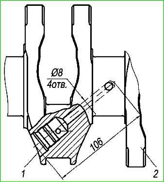
To remove deposits from the cavities of the connecting rod journals and oil channels, it is necessary to remove four plugs from the connecting rod journals, rinse with a solution of caustic soda (NaOH) heated to plus 80°C, and thoroughly clean the cavities and channels with a metal brush.
Rinse the cavities with kerosene and dry with compressed air, then screw the plugs into place with a torque of 37-51 N⋅m (3.8-5.2 kgf⋅m), having previously applied anaerobic sealant "Stop-9" to their threaded surface.
During operation, the main and connecting rod journals of the crankshaft wear out, lose their geometric shape, which reduces the performance of the crank mechanism, causes increased wear of the cylinders and piston rings, and the piston pin may push the circlips out of the grooves in the piston and cause the piston to come out pins from the piston.
The main and connecting rod journals of the crankshaft take the shape of a cone and oval as a result of wear.
If the main and connecting rod journals are worn beyond the maximum permissible dimensions and if the taper and ovality of the journals is more than 0.04 mm, then the shaft journals must be ground to one of the repair sizes.
All journals of the same name are ground to the same repair size. The sharp edges of the chamfers of the oil channels are blunted with a conical abrasive tool, and then the necks and chamfers are polished.
The radii of the fillets of the main and connecting rod journals are 2 mm.
If the surface of the rear flange or the surface of the damper pulley hub is worn under the working edge of the cuff, move the cuff to contact its working edge with the unworn surface and prevent oil leaks; to do this, install a spacer ring between the cuff and the oil seal holder or chain cover.
If the thread in the holes is damaged by up to two threads, it is restored by cutting it to the size of the working drawing. If two or more threads are broken, then repairs are carried out:
- thread in the holes for the flywheel mounting bolts - installation of threaded spiral inserts;
- thread in the hole for the coupling bolt - by cutting a repair thread;
- threads in holes for plugs - by cutting repair threads.
Controlled parameters when repairing the crankshaft
Diameter of main journals:
- - nominal diameter 62 −0.035−0.054 mm;
- - maximum permissible size 61.92 mm;
- - repair dimensions: 1 −0.25 mm; 2 −0.5 mm; 3 −0.75 mm
Diameter of connecting rod journals:
- - nominal diameter 56 −0.025−0.044 mm;
- - maximum permissible size 55.92 mm;
- - repair dimensions: 1 −0.25 mm; 2 −0.5 mm; 3 −0.75 mm
The greatest permissible runout of the main journals:
- - nominal diameter 0.02 mm;
- - maximum permissible size 0.04 mm;
Length of the third main journal between the two supporting surfaces of the thrust bearing:
- - nominal diameter 34 +0.050 mm;
- - maximum permissible size 34.06 mm;
Axial crankshaft clearance (thrust bearing):
- - nominal diameter 0.06-0.27 mm;
- - maximum permissible size 0.36 mm;
The greatest permissible ovality of the journals after grinding:
- - nominal diameter 0.005 mm;
- - maximum permissible size 0.01 mm;
Balancing
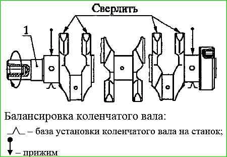
The crankshaft is balanced using the dynamic balancing method.
Permissible imbalance is 18 gcm, in planes passing through the outermost molar journals.
Eliminate imbalance by drilling holes Ø 14 mm, to a depth of no more than 25 mm in the radial direction from the counterweights.
Intersection of holes and exit to the surface of the ends of the counterweights is not allowed.
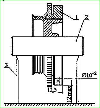
The crankshaft damper pulley is balanced using the static balancing method.
Permissible imbalance – 15 gcm.
Eliminate the imbalance by drilling holes Ø 10 mm, to a depth of no more than 12 mm, taking into account the drill cone in the damper disk in the radial direction at a distance of 10.5 mm from the rear plane.
The distance between the axes of the holes is at least 18 mm.
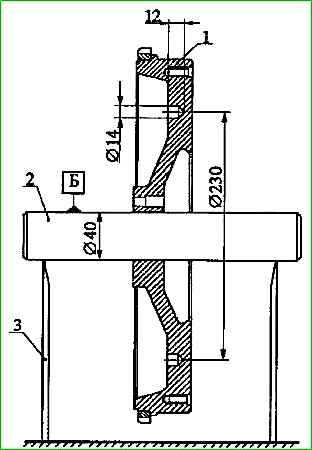
The flywheel is balanced using the static method. Permissible imbalance 15 gcm.
Eliminate the imbalance by drilling holes Ø 14 mm, to a depth of no more than 12 mm, taking into account the drill cone on the side opposite the clutch mount at a radius of 115 mm.
Drill no more than 10 holes. The distance between the axles is at least 18 mm.
")

")
")
")
")
")
")
")