Characteristics and possible malfunctions of the Kamaz-740.30-260 engine
Engines 740.30-260, manufactured in the "T" version according to GOST 15150-69, are designed for operation at ambient temperatures from minus 10 to plus 45 ° C, relative air humidity up to 80% at a temperature of 27 ° C and in areas where located at an altitude of up to 3000 m above sea level with a reduction in power, economic and other indicators up to 20%, with overcoming passes up to 4500 m.
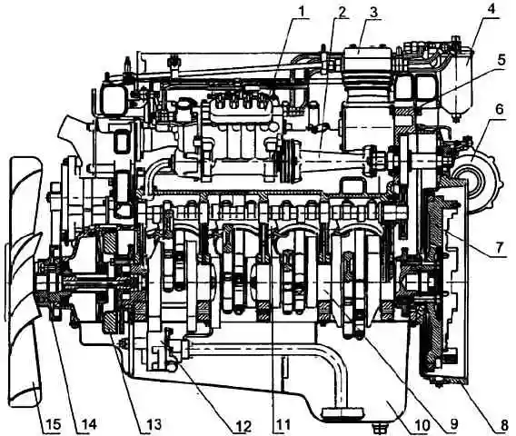
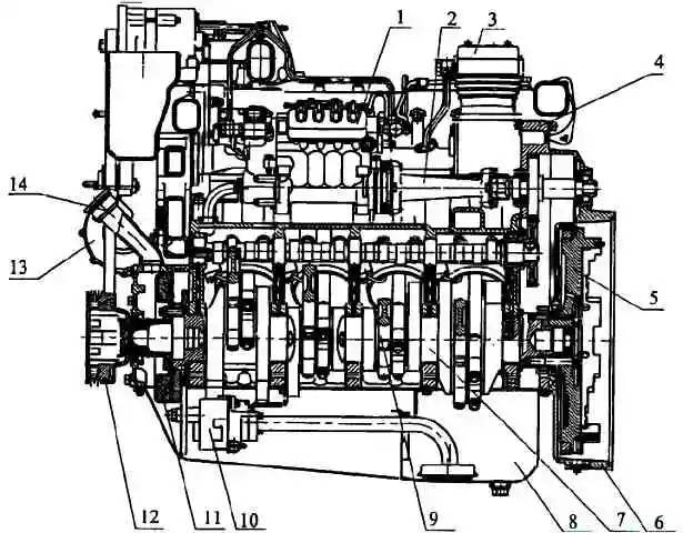
Longitudinal section of engine 740.30-260 (basic configuration): 1 - high pressure fuel pump; 2 - drive of the high pressure fuel pump; 3 - compressor; 4 - fine fuel filter; 5 - crankcase of units; 6 - turbocharger; 7 - flywheel; 8 - flywheel housing; 9 - crankshaft; 10 - oil sump; 11 - piston cooling nozzle; 12 - oil pump; 13 - torsional vibration damper; 14 - drive pulley for the water pump and generator; 15 - fan with viscous coupling
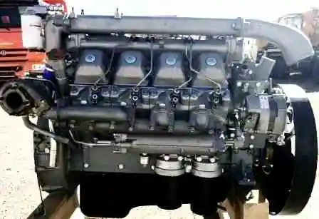
General view, longitudinal and transverse sections of the 740.30-260 engine are shown in Figures 1-5
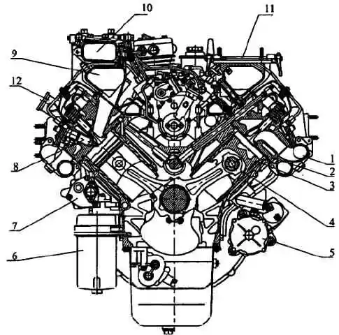
Cross-section of engine 740.30-260: 1 - exhaust manifold; 2 - cylinder head; 3 - cylinder block; 4 - piston; 5 - starter; 6 - oil filter; 7 - liquid-oil heat exchanger; 8 - nozzle; 9 - intake manifold; 10 - supply pipe; 11 - fuel injection pump regulator control drive; 12 - oil filler pipe
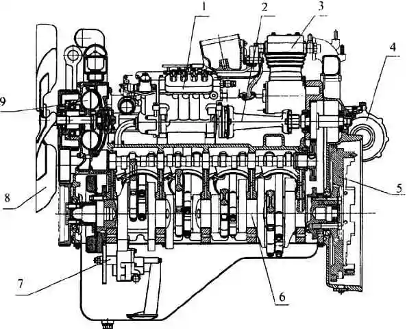
Longitudinal section of the engine 740.30-260 (with an overhead fan): 1 - high-pressure fuel pump; 2 - drive of the high pressure fuel pump; 3 - compressor; 4 - turbocharger; 5 - flywheel; 6 - crankshaft; 7 - oil pump; 8 - fan; 9 - fluid coupling
Longitudinal section of engine 740.30-260 (bus configuration): 1 - high pressure fuel pump; 2 - drive of the high pressure fuel pump; 3 - compressor; 4 - crankcase of units; 5 - flywheel; 6 - flywheel housing; 7 - crankshaft; 8 - oil sump; 9 - piston cooling nozzle; 10 - oil pump; 11 - torsional vibration damper; 12 - crankshaft pulley; 13 - turbocharger; 14 - oil filler pipe
In terms of their environmental performance, 740.30-260 engines meet the requirements of UNECE rules at the EVRO-2 level.
All necessary recommendations from the manufacturer on adjustments of the engine and its systems, main faults, methods for their detection and elimination are provided.
Information on chemmotology and standard products used in the design is provided.
Engine 740.30-260 four-stroke with compression ignition, liquid cooling, with a V-shaped arrangement of eight cylinders, with turbocharging and intercooling of the charge air (ONC) of the air-to-air type.
In terms of emissions of harmful substances from exhaust gases, the 740.30-260 engine complies with the requirements of UNECE Regulation No. 49-02 B (EURO-2).
The basic part of the engine is the cylinder block, on which the engine units and parts are installed and secured.
Wet-type cylinder liners are installed in the bore of the semi-blocks.
The cylinder liners are closed on top with heads, separate for each cylinder.
The cylinder block is closed from below with a stamped oil sump.
The camshaft is located in the cylinder block on five plain bearings.
The crankshaft is installed at the bottom of the block.
The engine cooling system is liquid, closed type, designed for the use of low-freezing coolant
Technical characteristics of the engine 740.30-260
Parameter name - Value
Engine type - Four-stroke, compression ignition
Cylinder arrangement is V-shaped, with a camber angle of 90°
The operating order of the cylinders is 1-5-4-2-6-3-7-8
The direction of rotation of the crankshaft is right (counterclockwise beams, when viewed from the flywheel)
Cylinder diameter and piston stroke, mm: 120x120
Working volume, l: 10.85
Rated power, kW (hp): 191 (260)
Maximum torque, Nm (kgf m): 1079 (110)
Setting angle of fuel injection advance, degrees: 9+1
Crankshaft rotation speed, min -1:
- - nominal 2200±50
- - at maximum torque 1200-1600
idling:
- - minimum 600±20
- - maximum 2530-80
The number of valves in the cylinder head is 2 (intake and exhaust)
Gaps on a cold engine, between the rocker arms and valve stems:
- - inlet - 0.25-0.30 mm;
- - graduation - 0.35-0.40 mm.
Oil pressure in a warm engine at crankshaft speed, kPa (kgf/cm 2):
- - nominal 392-539 (4-5.5)
- - minimum idle speed, not less than 98 (1)
Nozzle, type - 273
Models 273.1112010-21 (273-21)
Sprayer manufactured by "YAZDA" model 273.1112110-21 or 273.1112010-51 (273-51)
Sprayer manufactured by f. "BOSH" DLLA 148 SV3 142 323
Pressure at which the nozzle needle begins to rise, MPa (kgf/cm 2): 23.73...24.90 (242-254)
High pressure fuel pump (HPF) model 337-20
Fuel injection pump (bus equipment) model 337-71
The pressurization system is a gas turbine with two turbochargers and an air-to-air air-to-air coolant.
Generator model G-273V or 6582.3701 (in accordance with the design documentation) - three-phase synchronous, alternating current, with built-in rectifier unit
G-273V generator:
- - rated current, A; 28
- - rated rectified voltage, V; 28
- - rated power, kW. 0.8
Mod generator. 6582.3701:
- - rated current, A; 75
- - rated rectified voltage, V: 28
- - rated power, kW. - 2.0
Starter 5662.3708 DC, series excitation, with electromagnetic drive
rated power, kW 8.2
Possible malfunctions and solutions
Fault
- Cause of malfunction
Remedy
The engine does not start
- Lack of fuel in the tank
Fill the fuel tank, bleed the fuel supply system.
- Presence of air in the fuel supply system
Fix leaks, bleed the system.
- Violation of the fuel injection advance angle adjustment
Adjust angle.
- Freezing of water that gets into the fuel pipes or onto the fuel tank intake screen
Carefully warm the fuel filters, pipes and tank with a rag moistened with hot water or steam; do not use an open flame for heating
The engine does not develop the required power, it is unstable, there is smoke when it is running
- Clogged air cleaner or air intake hood
Service the air cleaner or clean the hood mesh
- Insufficient fuel supply
Replace the fine fuel filter elements, wash the coarse filter, tighten the connections in the fuel pipes.
- Violation of the fuel injection advance angle adjustment
Adjust angle.
- Clogging of the nozzle (coking of the nozzle holes, stuck needle) or violation of its adjustment.
Rinse the nozzle, replace the nozzle if necessary, check and adjust if necessary.
- Improper adjustment of the governor control lever drive (the control lever does not reach the bolt for limiting the maximum crankshaft rotation speed).
Check and adjust the regulator drive.
- Damage to the injection pump pusher spring.
Replace the spring and adjust the pump on the stand.
- Dirt between the seat and the valve of the fuel pump or spring breakage.
Rinse the valve or replace the spring, check the operation of the pump on the stand.
- Violation of the tightness of the injection valves or spring breakage.
Fix valve leakage in a workshop or replace the spring.
- Jamming of the injection pump section plunger
Replace the plunger pair and adjust the pump.
- Improper adjustment of thermal clearances in the gas distribution mechanism.
Adjust gaps.
- Depressurization of the membrane cavity or damage to the charge air pressure corrector membrane.
Restore the tightness of the membrane cavity or replace the damaged membrane.
- Stopping the oil supply to the charge air pressure corrector.
Restore the oil supply to the corrector.
- Loosening or breakage of the high pressure tube.
Tighten the fastening nut or replace the tube.
- Poor compression due to piston malfunctions group or loose fit of the gas distribution valves to the seats.
Check the condition of the pistons and piston rings, grind the valves.
- Fuel thickening (during cold periods).
Replace the fine fuel filter elements, replace the fuel with the appropriate fuel for the season, bleed the fuel supply system.
Low charge air pressure:
- air leakage through the connections of the intake manifold to the cylinder heads, pipes, turbochargers and compressor;
Tighten connections, replace gaskets and connecting hoses if necessary.
- gas breakthrough in the connections of the exhaust manifold and turbine housing;
Tighten connections, replace gaskets if necessary.
- jamming of the turbocharger rotor;
Replace the turbocharger.
- contamination of the exhaust tract, compressor and turbine flow parts.
Clean the pipelines, remove the turbocharger, and remove deposits from the flow parts.
Extraordinary noise in the turbocharger
- Rotor touching body parts
Tighten the bolts securing the turbine and compressor housings.
Check that there is no interference with the rotor at its extreme positions.
If the rotor gets caught, replace the turbocharger.
If the noise persists, remove the turbocharger for maintenance.
High frequency noise (whistle)
- The tightness of the engine intake and exhaust tracts is broken
Tighten the bolts and nuts securing the system parts, and replace the gaskets if necessary.
Increased oil consumption
- Long-term engine operation at idle speed.
Do not operate at engine idle speed unless necessary.
- Oil leakage through connections in the turbocharger lubrication system.
Tighten connections, replace gaskets and rubber sleeves if necessary.
- Wear of the valve-bushing interface in the cylinder head, aging of the rubber valve seal.
Check and replace worn parts.
- Clogged air cleaner or air intake hood.
Service the air cleaner and clean the hood mesh.
Reducing oil pressure in the lubrication system
- Low oil level in the oil sump.
Check and, if necessary, add oil to the “B” mark.
- Malfunction of pressure control devices
Make sure the devices are in working order.
- Use of oil of inappropriate viscosity
Replace the oil with one that corresponds to the chemical chart.
- Contamination of oil filter filter elements
Replace filter elements.
- Misadjustment or jamming of the safety valve or lubrication system valve
Check the valves and eliminate jamming, adjust or replace faulty parts if necessary.
- Clogged oil pump intake
Rinse the intake.
- Coolant getting into the oil
Check the tightness of the water cavity, the seal of the cylinder liners, the tightness of the water-oil heat exchanger, replace faulty parts.
- Oil leaks at joints and oil lines of the lubrication system
Check the condition of process plugs, plugs, tightness of fasteners at joints, condition of O-rings and gaskets.
- Oil pump malfunction
Remove the pump and check its functionality on a special stand.
- Unacceptable increase in clearance in crankshaft and camshaft bearings
Repair the engine.
Emergency oil temperature indicator lights up
- Malfunction of emergency oil temperature sensor
Make sure the sensor is working properly and replace it if necessary.
- Thermal valve for turning on the heat exchanger is stuck, the thermal power sensor is faulty
Check the operation of the thermal valve for turning on the heat exchanger, if necessary, eliminate jams or replace the sensor.
- Clogged tubes or dirty cooling plates
Check the water-oil heat exchanger for clogged tubes and contamination of the cooling plates, rinse or replace the heat exchanger if necessary.
Increasing oil pressure in the lubrication system
- High oil viscosity.
Replace the oil with one that corresponds to the chemical chart.
- Loss of tightness of the control signal line connecting the main oil line to the pump or its clogging
Check the oil supply pipe to the pump, the tightness of the mounting bolts, and the presence of a hole in the cover.
- Sticking or maladjustment of the lubrication system valve.
Check the valve and eliminate jamming, if necessary, replace faulty parts.
Knock when the engine is running
- Early injection of fuel into the cylinders.
Adjust the fuel injection advance angle.
- Increased thermal clearances in the gas distribution mechanism divisions
Adjust gaps.
- Wedging of the valves of the gas distribution mechanism in the bushings (the piston touches the valve)
Disassemble and wash the valve mechanism. Replace the valve if necessary.
- Increased cyclic fuel supply (rack lock disengaged)
Replace the injection pump rack
The knock of the crankshaft is dull. The frequency increases with increasing crankshaft speed
- Unacceptable increase in the gap between the journals and main bearing shells as a result of using inappropriate oil
specified in this manual, or reducing pressure and oil supply.
Grind the journals to the repair size and replace the bearings, change the oil and check the operation of the oil pump.
- Unacceptable increase in the gap between the thrust half-rings and the crankshaft.
Replace the thrust half-rings with new ones of greater thickness.
- Loosening the bolts securing the flywheel to the crankshaft.
Identify the cause and tighten the bolts.
The knock of the connecting rod bearings is sharper than the knock of the main bearings. It is heard when the engine is idling and intensifies with increasing crankshaft speed
- Unacceptable increase in the gap between the journals and shells of connecting rod bearings as a result of using inappropriate oil
specified, or reducing pressure and oil supply.
Grind the journals to the repair size and replace the bearings, change the oil and check the operation of the oil pump.
The knocking sound of the pistons is muffled and is caused by the beating of the pistons against the cylinders. Can be heard at low engine speeds and under load
- Unacceptable increase in the gap between the pistons and cylinders.
Replace the pistons and, if necessary, cylinder liners.
- Severe wear on the ends of the piston rings and the corresponding grooves on the piston.
Replace piston rings and, if necessary, pistons.
The knocking of the piston pins, double, metallic, sharp, is caused by a large gap. Better heard when the engine is idling
- Unacceptable increase in the gap between the pin and the bushing of the upper connecting rod head.
Replace the pin and, if necessary, the connecting rod.
Increased fluid temperature in the cooling system*
- Weak tension or broken water pump drive belts.
Tighten or replace belts.
- Thermostat malfunction
Replace thermostats.
- Contamination of the radiator core.
Clean the radiator core from dirt.
Increased coolant consumption
- Damage to the radiator
Repair damage or replace radiator
- Liquid leakage through the mechanical seal of the water pump.
Replace the mechanical seal.
- Coolant entering the lubrication system through the rubber sealing rings of the cylinder liners or through the rubber cylinder head gaskets.
Replace cylinder liner O-rings or rubber gaskets.
* Before looking for the cause of a malfunction in the lubrication system and cooling system, you need to make sure that the oil pressure and temperature gauges are working properly.
ELECTRIC FLARE DEVICE (EFD)
The EFU spark plug is faulty, the 30A fuse-link is burning
- Closing the thermal relay spiral or electrical wires
If the spark plugs are in good condition, disconnect the wire connecting it to the ECU power button from the thermal relay.
The absence of a short circuit when the ECU is turned on again indicates a short circuit of the thermal relay spiral. In this case, the thermal relay should be replaced.
If the thermal relay spiral is intact (determined by touch) and a short circuit occurs when the wires are disconnected from the spark plugs, then this indicates a short circuit in the electrical wires. Eliminate short circuit.
- Spark plug shorted to ground
Disconnect the wire from the left spark plug terminal, eliminating contact of the tip with ground, and turn on the EPI again. If shorted, disconnect the wire from the right spark plug terminal.
The absence of closure indicates the closure of the right candle. Replace the failed spark plug.
After eliminating the short circuit, it is recommended to check the condition of the insulation of the electrical wires, the operability of the thermal relay and the ECU turn-on relay, and if the short circuit occurs when starting the engine, the operability of the shunt relay
The ECU does not work, voltage does not flow to the ECU
- Thermal relay burnout
Turn on the ECU and check the voltage at the thermal relay terminals. The absence of voltage at the terminal on the side of the plug connection while there is voltage at the other terminal indicates a burnt-out spiral. Replace the thermostat.
- Burnt out spark plugs or lack of contact in the circuit
Turn on the EPI and check if there is voltage at the terminals of each EPI product, starting with the flare spark plugs. The presence of voltage at the terminal of the right spark plug indicates burnout of the spark plugs. Replace spark plugs or restore contact.
- Burnout of one of the candles
Turn on the EFU for 10-15 s, then replace ь cold candle.
No candle torch
- Lack of fuel supply to the spark plug
Loosen the fuel supply fitting on the spark plug. Turn on the ECU and after the indicator light comes on (opening of the solenoid valve), crank
using a starter, the crankshaft. If fuel does not leak through a loose threaded connection of the fitting when the valve is open, troubleshoot the fuel supply system.
- Failure of fuel to pass through the spark plug
Unscrew the spark plug from the manifold. Wash and blow out the nozzle, fuel filter and fuel supply cavities with compressed air. Check for the presence of a torch flame, for which:
- - connect the fuel pipe and electrical wires to the spark plug;
- - ensure a reliable connection of the spark plug body to ground and make sure that the terminal is isolated from ground;
- - turn on the ECU and use the starter to turn the crankshaft.
If there is no flame, replace the faulty spark plug.
Electrical equipment
The charge circuit indicator lamp lights up at the rated engine speed
- Relieving the tension of the generator drive belts
Adjust belt tension
- Contamination of slip rings
Wipe the rings with a cotton cloth moistened with pure gasoline. If the contamination cannot be removed, clean with glass sandpaper and wipe again with a napkin
- Wear or sticking of brushes in brush holders
Check the height of the brushes, their free movement in the channels of the brush holder and the force of the springs; if necessary, replace the brush holder or brushes
- Breakdown of the rectifier unit
Replace block
- Short circuit of the stator winding
Replace the stator assembly
- Disturbance in the excitation circuit
Check the serviceability of the excitation circuit
- Wear of bearing parts or their destruction
Replace generator
- Generator fan deformation
Straighten bent areas
Overheating of bearings
- Excessive belt tension
Adjust belt tension
Excessively rapid wear of generator brushes
- Contamination of slip rings
Wipe the rings with a cotton cloth moistened with pure gasoline. If necessary, clean with glass sandpaper and wipe again with a napkin
- Radial runout of slip rings
Check the radial runout of the rings. If necessary, sharpen the slip rings
Excessively high charging current
- Short circuit in the brush assembly of the generator or in the circuit between the generator and the regulator
Remove short circuit
- Malfunction of the voltage regulator
Replace regulator
- Malfunction of the generator field winding cut-off relay
Replace relay
Increased noise level during generator operation
- Loosening the pulley
Tighten the nut
- Lack of contact between brushes and commutator
Wipe the collector with a clean rag soaked in gasoline or clean it. Clean the brushes or replace them with new ones. Check status
brush springs and replace them if they are faulty. Check if the brushes are stuck in the brush holders
Starter does not work
- Short circuit or break in the pull-in winding of the traction relay
Replace relay
- Break or lack of contact in the power supply circuit
Find the location of the damage and restore contact
- Brushes stuck
Remove the brush holder, remove the brushes and remove brush dust
- Starter relay failure (738.3747-20)
Replace relay
- Open circuit inside the starter
Check and eliminate defects in the starter or replace the starter
The engine crankshaft does not turn with the starter (the traction relay is activated)
- Discharging batteries
Charge batteries
- Battery charging circuit failure
Fix the problem
- Malfunction of the voltage regulator
Replace regulator
- Oiling or contamination of the brush collector
Clean the commutator and brushes from oil, dirt, copper-graphite dust
- Poor contact of the starter housing with the mass of the power plant
Ensure connection reliability
- Using oil that is not appropriate for the season
Change oil
After the engine starts, the armature continues to rotate
- Traction relay malfunction
Replace relay
- Welding contacts of the starter relay (738.3747-20)
Replace relay
When the starter is turned on, the traction relay does not operate (there is no characteristic click)
- Battery low
Charge the battery
- Break in the pull-in winding of the traction relay
Replace relay
- Malfunction of the instrument switch and starter
Replace the switch
- Open or short circuit of the starter relay winding (738.3747-20)
Replace relay
The starter armature rotates, but does not turn the crankshaft
-Breakage of flywheel or gear teeth
Replace flywheel ring or drive gear
- Starter adjustment violation
Adjust the starter
- Drive fault
Replace drive
When the starter is turned on, repeated clicks of the traction relay and impacts of the drive gear on the flywheel rim are heard
- Unreliable contact of the starter traction relay circuit
Check the contact connections and eliminate the fault
- Malfunction of the holding winding of the traction relay
Replace the traction relay
- Malfunction of the winding or contact connection of the starter relay (738.3747-20).
Replace relay
When the starter is turned on, a noise (grinding) of the drive gear is heard
- Installing a starter with a skew
Install the starter correctly
- Incorrect adjustment of the closing torque of the traction relay contacts
Adjust the gap between the gear and thrust washer when the starter is turned on
The drive gear does not systematically engage with the flywheel ring during normal relay operation
- Presence of burrs on the ends of the teeth of the flywheel or drive gear
Filing and clearing burrs on the teeth of the flywheel crown or drive gear
- Wear of the ends of the teeth of the flywheel ring or drive gear
Replace flywheel ring or drive gear