We carry out the work on an inspection ditch or a lift
Remove the right wheel
We press out the ball pins of the rods from the holes of the pendulum arm: middle and side, article - “How to replace steering rods”

Using a 17mm socket, unscrew the lower bolt securing the pendulum arm bracket to the right side member

Keeping the nut from turning with a spanner of the same size.
In the same way, unscrew the upper bolt securing the bracket.

Remove the bolts

Remove the pendulum arm bracket.

Clamp the pendulum lever in a vice.
Use pliers to remove the cotter pin

Use a 19mm wrench to unscrew the adjusting nut

Remove the washer

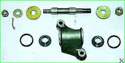
Remove the upper washer of the bracket body.

Remove the bracket body from the lever axis

Remove the upper and lower seals from the bracket body

Take out the upper plastic bushing of the axle and the lower one.

To replace the lever axis with a 22 wrench, unscrew the self-locking nut, holding the lever axis from turning with a 13 wrench

Remove the axle from the lever hole

Remove the lower washer
You can replace the plastic bushings and the axis of the pendulum arm bracket on the car without unscrewing the bolts securing the bracket to the side member.

Having disconnected the ball pins of the middle and side rods from the pendulum arm, unscrew the adjusting nut and remove the pendulum arm with the axle

Take out the plastic bushings.
Assemble the bracket in reverse order.
Tighten the self-locking axle nut to a torque of 63.7-102.9 Nm (6.5-10.5 kgf m).
Lubricate the plastic bushings and fill the cavity between them in the bracket with Litol-24 grease.
Install the upper washer with the extrusions facing up.
After tightening the adjusting nut, the lever should rotate under the influence of a force of 9.8–19.6 N (1–2 kgf) applied at its end.
If the turning force of the lever exceeds this value, then unscrew the adjusting nut, lift the top washer and tighten the nut again so as to achieve the required turning force of the lever.
Tighten the nuts of the bolts securing the pendulum arm bracket with a torque of 33.3-41.2 Nm (3.4-4.2 kgf m)
")

")
")
")
")
")
")
")