We hang the rear part of the car on tripods, remove the rear wheel and brake drum
We use a jack to lift the disassembled edge of the rear axle beam so that the oil does not spill out after removing the axle shaft.
We remove the brake pads from the side of the axle shaft being removed (see the article - "Replacing the brake pads").

Using a 17 mm wrench, unscrew the four nuts securing the axle shaft to the beam flange.

Using a screwdriver, bend back the locking plates of the axle shaft mounting bolts.

Removing the bolts

Fix an impact puller on the axle shaft flange and knock the axle shaft out of the beam.

If there is no puller, then we fix the wheel with the back side on the half-shaft, bait three nuts for several turns

Holding the wheel, we jerk the axle shaft

We take out the axle shaft

We take out the sealing rubber ring of the beam flange

We insert two bolts into the holes of the brake shield and the rear axle beam so that the shield does not hang on the brake pipe

We pry off the oil seal with sliding pliers

And take it out

Using a head of a suitable size with an extension or a piece of pipe, press in a new oil seal
Install the half-shaft in the reverse order.
Check the oil level in the rear axle and top up if necessary.
Checking the technical condition and repairing the half-shaft
After dismantled the axle shaft, you need to check its condition and the condition of the parts included in the axle shaft kit. You need to make sure that:
- - the ball bearing is not worn or damaged; if the axial clearance in it exceeds 0.7 mm, replace thread the bearing;
- - the retaining ring and the bearing have not shifted relative to the original fit; if the inner ring of the bearing rotates relative to the seating belt of the axle shaft, replace the retaining ring;
- - the bearing mounting plate and oil deflector are not damaged;
- - the axle shaft is not deformed and the seating surfaces are not damaged; The runout of the axle shaft, measured in the centers on the journal under the oil seal, should not exceed 0.08 mm.
Before installing in the centers, thoroughly clean the centering holes on the axle shaft from dirt and rust.
If wear or damage to parts installed on the axle shaft is detected, replace them with new ones in compliance with the rules below and using special devices.
Remove minor bending of the axle shaft rod by straightening.
After straightening the axle shaft rod, the runout of the flange topper, measured in the centers, should not exceed 0.05 mm.
If the runout of the flange end is higher than specified, but not more than 0.08 mm, then it is allowed to machine it to eliminate the end runout.
A decrease in the flange thickness due to its machining is allowed by no more than 0.2 mm.
Removing the retaining ring
Removing and installing the axle bearing retaining ring must be done using a hydraulic press only.
Pre-bend outward the holders of the bolts securing the plate with the oil deflector and the brake shield, and remove the bolts.
Use the half rings of the 67.7823.9529 device to encircle the bearing and install the axle shaft vertically so that the half rings rest on the thrust ring.
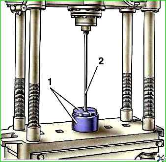
Place the axle shaft under a press (Fig. 13) and apply gradually increasing force to the splined end of the axle shaft until the bearing retaining ring is removed.
Do not reuse the axle shaft bearing retaining ring, but replace it with a new one.
Check that the axle shaft seating surface has no scratches or damage; if necessary, replace the axle shaft with a new one.
Assembling the axle shaft
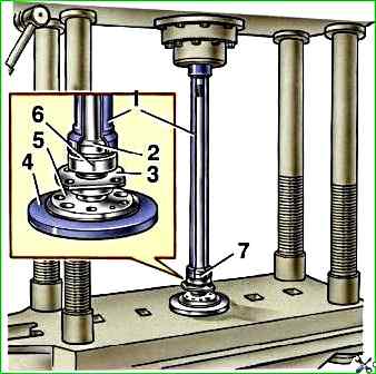
Place the axle shaft vertically, resting its flange on wheel 7 (Fig. 14) of device 67.7823.9530.
Install the axle shaft bearing oil deflector and bearing mounting plate with gasket, previously connected to each other with two screws, on the axle shaft; install the axle shaft ball bearing.
Insert the new locking ring into the special holder 3, place it in the oven and heat the ring to approximately 300° C so that when it is pressed onto the axle shaft, its temperature is 220-240° C.
Press the locking ring onto the axle shaft using mandrel 1 on a press with a force of no more than 58.8 kN (6000 kgf) so that the inner bearing ring is clamped between the locking ring and the axle shaft flange.
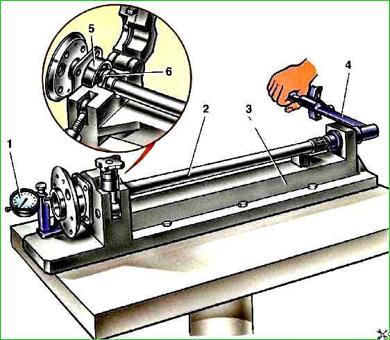
After pressing, make sure that the ring does not shift under an axial load of 19.6 kN (2000 kgf).
For this purpose, install the axle shaft assembly on a special device (Fig. 15), and clamp the locking ring in a special vice.
Attach the indicator leg 1 with a division value of 0.01 mm to the axle shaft flange.
After setting the indicator arrow to "0", apply the specified axial load, creating a tightening torque of 78.5-83.3 Nm (8-8.5 kgf m) with a torque wrench on the device screw.
The screw rests against the end of the axle shaft through the ball. In this case, there should not be even the smallest gap between the locking ring and the inner ring of the bearing.
After removing the load and unscrewing the screw of the device, the indicator arrow should return to the zero position; this proves that no shift has occurred between the locking ring and the axle shaft.
If the indicator arrow does not return to the zero position, then the locking ring the ring has shifted and the axle shaft assembly must be replaced with a new one.
After checking the pressing of the locking ring, install the plate and oil deflector mounting bolts 6 (Fig. 14) and secure them by bending the bolt holders inward.
Measuring the axial free play of the axle shaft on the vehicle
Loosen the rear wheel mounting nuts.
Place stops under the front wheels and remove the rear axle.
Release the parking brake and set the gear shift lever to neutral.
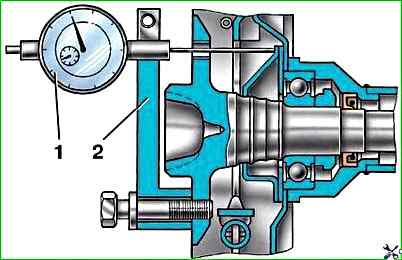
Remove the wheels and brake drums, screwing device 02.7834.9504 to the axle shaft (Fig. 16), pass the extension of the indicator leg 1 through one of the holes in the axle shaft until it stops against the brake shield or oil deflector and secure the indicator.
Take measurements with an indicator, applying a force of about 49 N (5 kgf) to the axle shaft flange in both directions along the rear axle axis.
Free play should not exceed 0.7 mm.
")

")
")
")
")
")
")
")