The VAZ-21213 engine is equipped with a generator of type 371.3701, and the VAZ-21214 engine is equipped with a generator of type 9412.3701
These generators are structurally similar and are synchronous electric machines of alternating current with electromagnetic excitation, with a built-in rectifier on silicon diodes and an electronic voltage regulator.
Technical characteristics of generators 371.3701 and 9412.3701
- Generator type 371.3701
- Maximum output current (at 13 V and 6000 min -1) - 55 A
- Voltage - 13.6–14.6 B
- Direction of rotation (from the drive side) is right
- Generator type 9412.3701
- Maximum output current (at 13 V and 6000 min -1) - 80 A
- Voltage - 13.2–14.7 V
- Direction of rotation (from the drive side) is right
The generator rotor is driven from the engine crankshaft pulley by a V-belt.
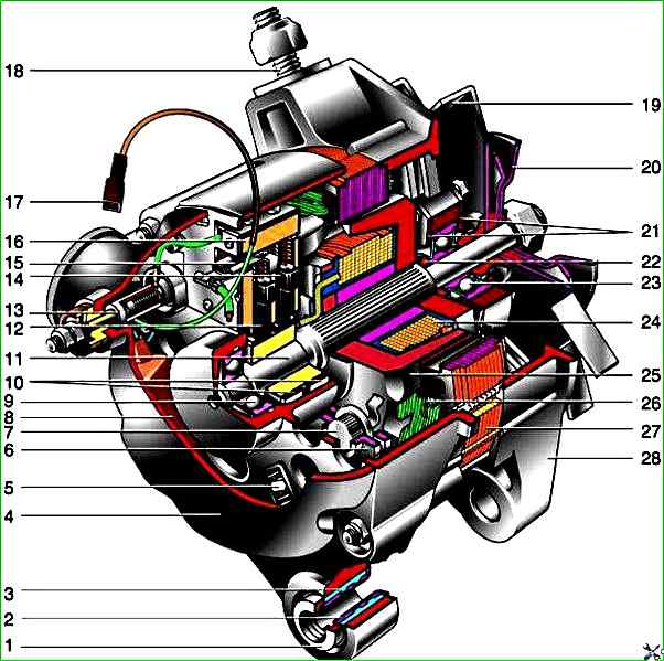
Generator 371.3701: 1 - pressure sleeve; 2 - sleeve; 3 - buffer sleeve; 4 - protective casing; 5 - rectifier unit fastening screw; 6 - rectifier unit; 7 - rectifier unit valve; 8 - capacitor; 9 - rotor shaft rear bearing; 10 - slip rings; 11 - rotor shaft; 12 - brush connected to terminal "B" of the voltage regulator; 13 - terminal "30" for connecting consumers; 14 - brush connected to terminal "Ш" of the voltage regulator; 15 - terminal "B" of the voltage regulator; 16 - voltage regulator; 17 - terminal "61" of the generator; 18 - stud for fastening the generator to the tension bar; 19 - impeller; 20 - pulley; 21 - bearing mounting plates; 22 - thrust ring; 23 - rotor shaft front bearing; 24 - rotor winding; 25 - rotor pole piece; 26 - stator winding; 27 - stator; 28 - front cover
The stator and covers of the generator are tightened with four bolts.
The rotor shaft rotates in bearings installed in the covers.
The grease put into the bearings at the factory is designed for the entire service life of the generator.
The rear bearing of the generator 9412.3701 is pressed onto the rotor shaft and is pressed by the rear cover through a plastic bushing, the front bearing is pressed and rolled into the front cover and is replaced only together with it.
Its inner race together with the thrust ring and washer is clamped with a nut between the pulley and the step on the rotor shaft.
The front bearing of the generator 371.3701 is tightened with four screws between the inner and outer plates and can be replaced separately from the front cover.
The rear part of the 9412.3701 generator is covered with a plastic casing with latches.
On the rear cover of the 371.3701 generator, a casing with a rubber air intake is installed, allowing air to be taken in for cooling the generator from the upper part of the engine compartment, which reduces the likelihood of water getting into the generator when driving through deep puddles and fords.
On the 21214 engine, this danger is less, since instead of a mechanical fan of the cooling system (which inevitably splashes water), electric fans are installed there, moreover, they are located in front of the radiator.
A three-phase winding is located in the generator stator, made according to the "star" scheme (the terminals of the phase windings have a common point).
The second ends of the phase windings are connected to the rectifier bridge, consisting of six silicon diodes (valves) - three "positive" and three "negative".
The valves are pressed into two horseshoe-shaped aluminum holder plates in accordance with polarity (positive and negative - on different plates); One of the plates also contains three additional diodes, through which the excitation winding of the generator is powered after the engine is started.
The plates are combined into a rectifier unit, fixed on the rear cover of the generator (under the plastic casing of the generator 9412.3701).
The excitation winding is located on the generator rotor, its terminals are soldered to two copper contact rings on the rotor shaft.
Power is supplied to the excitation winding through two carbon brushes.
The contact rings of the generator 9412.3701 are of reduced diameter - this reduces the peripheral speed of rotation and reduces brush wear.
The brush holder is structurally combined with the voltage regulator and is fixed on the rear cover of the generator.
The voltage regulator is non-separable, if it fails, it is replaced.
Before 1996, the 371.3701 generator had a brush holder and voltage regulator that were separate units (the control voltage from terminal "30" of the generator was supplied to terminal "B" of the voltage regulator).
Now the voltage is supplied only to terminal "B" (terminal "B" is missing).
The new and old voltage regulators are identical in their characteristics and are assembled with brushes The holder is interchangeable.
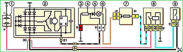
Generator 371.3701 wiring diagram: 1 - battery; 2 - generator; 3 - instrument cluster; 4 - 51 Ohm, 5 W resistor; 5 - diode; 6 - battery charge indicator lamp; 7 - fuse box; 8 - ignition relay; 9 - ignition switch.
To protect the on-board network from voltage surges during ignition system operation and to reduce interference with radio reception, a capacitor with a capacity of 2.2 μF +-20% is connected between the terminals of the "positive" and "negative" valves (between the "+" and "ground" of the generator), located on the rectifier unit of the generator 9412.3701 and the rear cover of the generator 371.3701.
When the ignition is turned on, voltage is supplied to the excitation winding of the generator (terminal "D" of the generator 9412.3701 and "B" of the generator 371.3701) through the control lamp in the instrument cluster (the lamp is on) and the resistors connected in parallel to it.
After starting the engine, the excitation winding is powered by additional diodes of the rectifier unit (the control lamp goes out).
If the lamp lights up after starting the engine, this indicates a malfunction of the generator or its circuits.
The "minus" of the battery must always be connected to the "ground" of the car, and the "plus" - to the "B+" terminal of the generator 9412.3701 (terminal "30" - generator 371.3701).
Reverse connection will lead to breakdown of the generator valves. When the generator is running, it is not recommended to disconnect the battery (especially on engines equipped with an injection system).
The resulting voltage surges in the on-board network can damage the electronic components of the circuit.
The generator valves (and other devices in the vehicle's on-board network with the generator connected) should be checked under a voltage of no more than 14 V, a higher voltage (for example, when checking with a megohmmeter) can cause damage to the valves.
If it is necessary to check the insulation of the windings with high voltage, the generator should be removed, and the winding terminals should be disconnected from the rectifier unit and voltage regulator.
Checking the generator
Start the engine, let it run for a few minutes, then, pressing the gas pedal, bring the crankshaft speed to 3000 min –1 .
Turn on the high beam headlights, Rear window heating, heater fan.
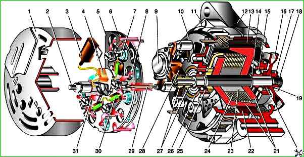
Generator 9412.3701: 1 - casing; 2 - terminal "B+" for connecting consumers; 3 - capacitor; 4 - common terminal of additional diodes (connected to terminal "D+" of voltage regulator); 5 - holder of positive diodes of rectifier unit; 6 - holder of negative diodes of rectifier unit; 7 - positive diode; 8 - negative diode; 9 - voltage regulator; 10 - rear cover; 11 - tightening screw; 12 - front cover; 13 - stator winding; 14 - thrust ring; 15 - rotor shaft front bearing; 16 - pulley; 17 - nut; 18 - rotor shaft; 19 - conical washer; 20 - washer; 21 - rotor pole pieces; 22 - stator core; 23 - sleeve; 24 - rotor winding; 25 - rotor shaft rear bearing; 26 - bearing sleeve; 27 - slip rings; 28 - brush holder; 29 - stator winding terminals; 30 - additional diode; 31 - terminal "D" (common terminal of additional diodes)
Measure the voltage at the terminals of the battery, which should be higher than 13.2 V for the 9412.3701 generator and 13.6 V for the 371.3701 generator.
If this is not the case, the voltage regulator with the brush assembly, the generator windings (open or short circuit) are faulty, or the contact rings of the excitation winding are oxidized.
To make sure that the voltage regulator is working properly, turn off all consumers except the high beam headlights and measure the voltage again.
It should be within 13.2–14.7 V for the 9412.3701 generator and 13.6–14.6 V for the 371.3701.
The removed voltage regulator of the generator 9412.3701 can be checked by connecting a lamp (1–5 W, 12 V) between the brushes, and a power source (only direct current, “minus” to “ground”!) to the terminals “D+” and “ground”, first with a voltage of 12 V, and then 15–16 V.
In the first case, the lamp should light, in the second - not.
If the lamp lights in both cases, there is a breakdown in the regulator, if it does not light - there is a break or the contact between the brushes and the terminals of the regulator is broken.
In both cases, the regulator should be replaced.
To check the generator regulator 371.3701, the current source should be connected to terminals “B” and “C” (“plus”) and “ground” (“minus”).
To check rectifier block valves, disconnect the wires from the battery batteries, generator and from the terminal(s) of the voltage regulator.
Connect the “plus” of the battery via a lamp (1–5 W, 12 V) to the “B+” terminal of the 9412.3701 generator (to the “30” terminal of the 371.3701 generator), and the “minus” to its body.
If the lamp lights up, then there is a short circuit in both the “positive” and “negative” valve blocks.
To check for a short circuit in the “positive” valves, connect the “plus” of the battery via a lamp to the “B+” terminal of the 9412.3701 generator (to the “30” terminal of the 371.3701 generator), and the “minus” to the terminal of one of the phase windings of the stator.
If the lamp lights up, one or more positive valves.
To check for a short circuit in the "negative" valves, connect the "plus" of the battery via a lamp to the terminal of one of the phase windings of the stator, and the "minus" to the generator housing.
If the lamp is on, one or more negative valves are broken or the stator windings are shorted to the generator housing.
To exclude a short circuit in the windings, remove the generator from the car and, having disconnected the windings from the voltage regulator and rectifier unit, check their short circuit to "ground" with a lamp or ohmmeter.
The generator valves can also be checked with an ohmmeter, without connecting the battery and test lamp.
The short circuit of additional diodes can be checked by connecting the "plus" of the battery via a lamp to the "D" terminal of the 9412.3701 generator (to the "61" terminal of the 371.3701 generator), and the "minus" - to the terminal of one of the phase windings of the stator (to one of the bolts of the rectifier unit).
If the lamp is on, one or more additional diodes are broken.
A break in the main valves is determined by a sharp decrease in the output current (voltage drop under load).
This can also be caused by a break or short circuit in the generator windings.
A break in the additional valves can be determined by low voltage on the "D" plug of the 9412.3701 generator or the "61" plug of the 371.3701 generator (below 14 V) at low and medium rotation speeds of the generator rotor.
The serviceability of each diode (main or additional) can only be determined on the removed rectifier unit using an ohmmeter or a test lamp.
If the rectifier unit fails, it is recommended to replace as a whole.
Individual valves may be replaced, but the main valves will require re-pressing in the holder - an operation that requires accuracy and skill.
The stator and rotor windings are checked with a special flaw detector or electronic oscilloscope - based on the shape of the voltage curves.
")

")
")
")
")
")
")
")