Steering – with mechanical linkage, without amplifier. Steering mechanism - "globoidal worm - double-ridge roller", gear ratio - 16.4
The steering linkage is formed by three steering rods (one middle and two side), a bipod, a pendulum arm and steering knuckle arms.
The side rods consist of two tips connected by a threaded split coupling.
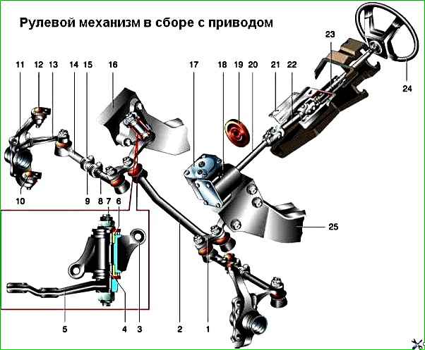
Steering mechanism assembly with drive: 1 - bipod; 2 - average thrust; 3 - housing of the pendulum arm bracket; 4 - lever axis; 5 - pendulum lever; 6 - bushing; 7 - adjusting nut; 8 - inner rod end; 9 - adjusting clutch; 10 - lower ball joint; 11 - steering knuckle; 12 - upper ball joint; 13 - rotary lever; 14 - outer rod end; 15 - clamp; 16 - right spar; 17 - upper crankcase cover; 18 - steering gear housing; 19 - seal; 20 - worm shaft; 21 - shaft bracket; 22 - intermediate shaft; 23 - upper shaft; 24 - steering wheel; 25 - left spar
On the internal (short) tip there is a right-hand thread, on the external one there is a left-hand thread.
The threads on the coupling are also of different directions, so when you turn it, the length of the side rod can increase or decrease, which is necessary to adjust the toe-in of the wheels.
The coupling is fixed on the ends with clamps.
At the ends of the steering rods there are ball joints. Their fingers have a conical fit in the levers and are fixed in them with nuts and cotter pins.
The ball head of the pin rotates in a plastic insert, pressed by a spring to the hinge body.
The other end of the spring rests against a steel plug rolled into the hinge body.
Due to the taper of the outer surface of the liner and the inner surface of the hinge body, when the liner is pressed, a backlash is selected between the liner and the ball head of the pin.
To make sure that the liner is not jammed in the body, press the hinge body in the direction of the finger with your hand or a mounting blade - the finger should go 0.5–1.5 mm inside the body.
If the hinge jams or there is noticeable play in it, replace the tie rod (steering end).
The hinge is protected from moisture and dirt by a rubber cover pressed onto the body.
If the cover is damaged, immediately replace it by removing old grease from the joint surface and adding new one (ShRB-4).
The swing arm bracket is attached to the right side member with two bolts and self-locking nuts.
The bracket body is cast, made of aluminum alloy. It contains two plastic bushings in which the axis of the pendulum arm rotates.
The axle is fitted with washers on top and bottom, which press the bushings against the bracket body.
The lower washer rests against the pendulum arm, secured to the axle with a self-locking nut, the upper one rests against the nut with a cotter pin.
This nut is tightened on the removed bracket so that the pendulum arm does not rotate under its own weight, but only under a load of 1–2 kgf.
Litol-24 lubricant is placed on the working surfaces of the bushings and in the space between the axle and the body.
To protect against dirt, two rubber O-rings installed between the washers and the lever body are used.
When the bushings are worn, they are replaced, and when the body or axle is worn, the bracket is replaced.
The steering mechanism is attached with three bolts with self-locking nuts to the left side member. Its body is cast aluminum alloy.
Two bronze bushings are pressed into its lower (elongated) part, in which the steering bipod shaft rotates.
The steering bipod is secured with a nut at the lower splined end of the shaft (it is installed on the shaft only in a certain position).
On the top of the shaft there is a boss with a cutout; it contains a double-ridge roller rotating in ball or needle bearings.
The T-shaped groove on the upper end of the shaft includes the head of a screw, which adjusts the gap between the roller and the worm (see below).
The axial play of the head in the groove should not exceed 0.05 mm; this is achieved by selecting the thickness of the adjustment plate placed on the screw.
The screw moves along the threads in the steering mechanism cover and is locked with a nut and a shaped washer.
The worm of the steering mechanism rotates in two angular contact ball bearings, the gap in which is adjusted by selecting gaskets between the body and the bottom cover (in this case, oil pours out of the mechanism; after adjustment, its level must be restored).
With a correctly adjusted gap, the torque of turning the worm shaft (with the bipod shaft removed) should be in the range of 20–49 N.cm.
If it is smaller, reduce the thickness of the gasket package; if it is larger, increase it.
After installation The bipods regulate the gap in the engagement of the roller with the worm: the moment of resistance to turning the worm shaft when turning 30° to the right-left from the middle position should be 88–118 N.cm, and at large angles - no more than 69 N.cm.</p >
In practice, the simplest control is as follows: with the steering mechanism removed, the worm shaft should rotate by hand with a noticeable increase in force near the middle position; there should be no axial play of the shaft.
To fill the steering gear housing with oil, there is a hole in the top cover that is closed with a screw plug.
Gearbox oil is poured to the edge of this hole (0.215 l), and the level is checked using it.
Oil leakage is possible from under the lower cover of the worm shaft bearing (due to its deformation) or through the oil seals of the bipod and worm shafts.
Repairing the gearbox at home (except for adjusting gaps and replacing seals) is not recommended.
The steering shaft is a two-link shaft, consisting of an upper and an intermediate shaft.
The upper shaft rotates in two bearings with rubber bushings, rolled into the shaft bracket pipe.
In the lower part, a ring with a groove is welded to the shaft, into which the locking bolt of the anti-theft device fits.
The steering wheel is attached to the upper splined end of the shaft, its fastening nut is cored.
The intermediate shaft has cardan joints at the ends with split spline ends, tightened with bolts; the lower one is connected to the worm shaft, the upper one is connected to the upper steering shaft.
Injury safety of the steering is ensured by folding the steering shaft due to universal joints and special fastening of the steering shaft bracket.
The latter is attached to the body bracket at four points: at the top - on welded bolts with nuts and washers, at the bottom - with special tear-off bolts with fixing plates.
In a collision, the edges of the fixing plates are deformed and slip through the rectangular holes in the steering shaft bracket.
At the same time, due to the folding of the steering shaft, the steering wheel does not move back, but up and forward, reducing the likelihood of injuries to the driver’s chest.
Possible steering malfunctions and solutions
Cause of malfunction - Elimination method
Increased free play of the steering wheel
The steering gear housing mounting bolts are loose - Tighten the nuts
The ball pin nuts are loose - Check and tighten the nuts
Increased clearance in tie rod ball joints - Replace tie rod ends or tie rods
Increased clearance in the front wheel hub bearings - Adjust the clearance
Increased gap in the engagement of the roller with the worm - Adjust the gap
The gap between the swing arm shaft and the bushings is too large - Replace the bushings or bracket assembly
Increased clearance in the worm bearings - Adjust the clearance
The bolts securing the intermediate shaft to the worm shaft or to the upper steering shaft are loose - Tighten the bolts
Tight rotation of the steering wheel
deformation of steering gear parts - Replace deformed parts
Incorrect front wheel alignment - Check wheel alignment and adjust
The gap in the engagement of the roller with the worm is broken - Adjust the gap
The adjusting nut of the pendulum arm axis is overtightened - Adjust the tightening of the nut
Low pressure in front tires - Set normal pressure
Damage to ball joint parts - Check and replace damaged parts
There is no oil in the steering gear housing - Check and add. If necessary, replace the oil seal
Damage to upper steering shaft bearings - Replace bearings
Noise (knocking) in the steering
Increased clearance in the front wheel hub bearings - Adjust the clearance
Loosening the tie rod ball pin nuts - Check and tighten the nuts
Increased clearance between swingarm shaft and bushings - Replace bushings or bracket assembly
The adjusting nut of the pendulum arm axis is loose - Adjust the tightening of the nut
The clearance in the engagement of the roller with the worm or in the worm bearings is broken - Adjust the clearance
Increased clearance in tie rod ball joints - Replace tie rod ends or tie rods
Loosening the steering gear housing or swing arm bracket bolts - Check and tighten the bolt nuts
Loosening the swing arm nuts - Tighten the nuts
Loosening the steering intermediate shaft bolts - Tighten the bolt nuts
Self-excited angular oscillation of the front wheels
Tire pressure is not correct - Check and set normal pressure
The front wheel alignment angles are incorrect - Check and adjust the wheel alignment angles
Zoom in The gap in the front wheel hub bearings is correct - Adjust the gap
Wheel imbalance - Balance the wheels
Loosening the tie rod ball pin nuts - Check and tighten the nuts
Loosening the steering gear housing or swing arm bracket bolts - Check and tighten the bolt nuts
The gap in the engagement of the roller with the worm is broken - Adjust the gap
Driving the vehicle from straight-line motion in any one direction
Uneven tire pressure - Check and set the correct pressure
The front wheel alignment angles are incorrect - Check and adjust the wheel alignment angles
Different spring settlement of the front suspension - Replace unsuitable springs
The steering knuckles or suspension arms are deformed - Check the knuckles and levers, replace unsuitable parts
Incomplete release of one or more wheels - Check the condition of the brake system
Car instability
The front wheel alignment angles are incorrect - Check and adjust the wheel alignment angles
Increased clearance in the front wheel bearings - Adjust the clearance
Loosening the tie rod ball pin nuts - Check and tighten the nuts
Tie rod ball joint play too large - Replace tie rod ends or tie rods
Loosening the steering gear housing or swing arm bracket bolts - Check and tighten the bolt nuts
Increased gap in the engagement of the roller and worm - Adjust the gap
The steering knuckles or suspension arms are deformed - Check the knuckles and arms; replace deformed parts
Oil leak from crankcase
Wear of the bipod or worm shaft seal - Replace the seal
Loosening the bolts securing the steering gear housing covers - Tighten the bolts
Damage to sealing gaskets - Replace gaskets