In some vehicle configurations, it is possible to install an electromechanical power steering
The main differences between such a power steering and a hydraulic power steering are: no part of the engine power is taken to drive the pump; there is a possibility of differentiating the force on the steering wheel depending on the speed of the vehicle (feedback).
The electromechanical amplifier is installed on the steering column and acts directly on the steering shaft.
For joint operation with the electromechanical amplifier, a steering gear is installed on the vehicle, similar in design to the mechanism of the VAZ-2123 "Niva" vehicle, but having a number of improvements that increase its reliability and accuracy of operation.
Removing and installing the steering column

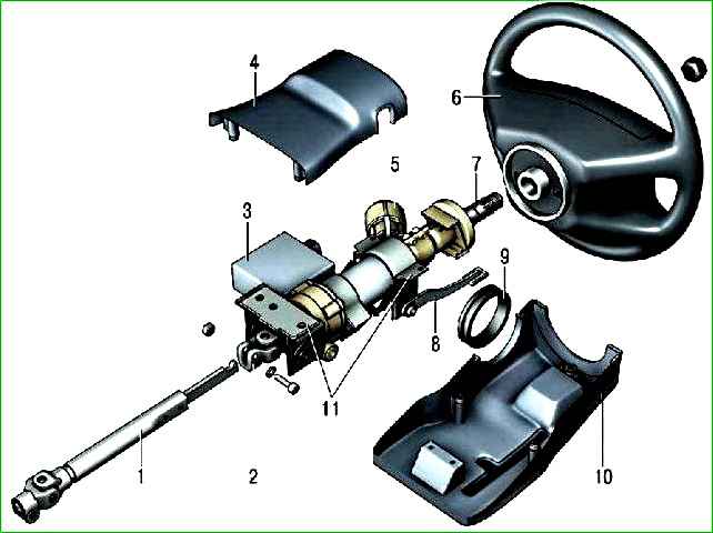
The elements of the steering column with electromechanical booster are shown in Fig. 1.
In the engine compartment, unscrew the nut of the clamping bolt securing the lower end of the intermediate shaft 1 (Fig. 1) to the steering gear worm shaft and remove the clamping bolt.
In the car's interior, unscrew the screws securing the steering column shaft seal and remove it.
Remove the steering column trim covers 4 and 10.
Disconnect the connectors with wires from the steering column switches, ignition switch and electromechanical amplifier. 5.
Unscrew the bolts and nuts securing the steering column and remove it together with shafts 1, 7 and steering wheel 6.
If necessary, remove the electromechanical amplifier from the steering column and check its operation according to the separate manual for the amplifier supplied with the vehicle.
Install the steering column in the reverse order of removal.
Removing and installing the steering gear
The steering gear is removed for replacement or repair.
Disassembling and assembling the mechanism requires the use of special tools and the operator having the necessary skills.
If these conditions are not met, we recommend repairing the steering gear in a specialized workshop.
Place the vehicle on a lift or inspection pit.
Disconnect the wire from the “–” terminal of the battery.
Unscrew nut of the clamping bolt securing the lower end of the intermediate shaft 1 (see Fig. 1) to the steering gear worm shaft and remove the clamping bolt.
Remove the cotter pins of the nuts securing the ball joint pins to the pitman arm and unscrew the nuts.
Use a puller to press the ball pins out of the pitman arm holes.
Unscrew the nuts of the bolts securing the steering gear to the body side member and remove the steering gear.
Install the steering gear in the reverse order of removal, and do the following:

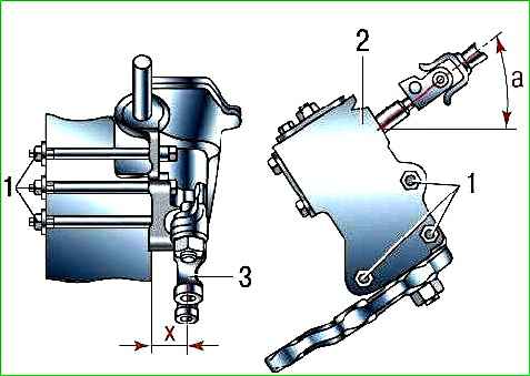
- – set the steering knuckle to the middle position, while the mark on the end of the worm shaft should be located horizontally on the right (in the direction of vehicle travel) and the distance X (Fig. 2) from the center of the lower hole of the knuckle to the support surface on the body side member should be (33.1+5) mm;
- – before tightening the nuts of bolts 1, orient the steering gear so that the angle a is 32°;
- – check and, if necessary, adjust the installation angles of the front wheels.
Disassembling and assembling the steering gear
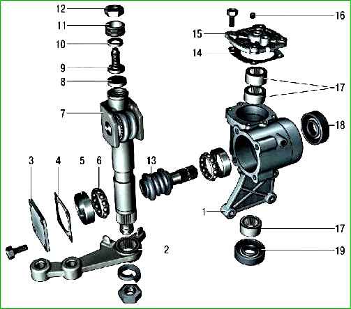
Drain the oil from the steering gear by unscrewing plug 16 (see Fig. 3) of the oil filler hole and turning the mechanism upside down.
Unscrew the fastening nut steering knuckle and, having removed the spring washer, remove the knuckle with a special puller.
Unscrew the mounting bolts and remove the cover 15 of the steering gear housing together with the shaft 7 of the knuckle.
Unscrew the nut 12 and, screwing the adjusting screw 9 into the cover 15, separate the cover and the shaft 7 of the knuckle.

Unscrew the fastening bolts and remove the cover 3 of the worm shaft thrust bearing together with the adjusting linings 4.
Using the worm 13, push the outer ring 5 of the bearing out of the housing and remove the shaft together with the bearing separator 6.
Remove the worm shaft oil seal 18 and the pitman arm shaft oil seal 19 from the housing 1.
Using a mandrel of suitable size, press the outer ring of the upper worm shaft bearing out of the housing.
Remove the bearings 17 from the housing 1 and the cover 15.
Carefully inspect the working surfaces of the roller and worm for signs of wear, seizure or risk. Replace worn and damaged parts.
The worm and roller ball bearings must rotate freely, without jamming; the surface of the rings and balls must be free of wear and damage.
Replace damaged bearings with new ones. If the roller rotates on the axis with jamming or has play, replace the pitman arm shaft assembly with the roller.
Assemble the steering gear in the reverse order of removal, observing the following conditions:
- – after installing the worm in the steering gear housing and securing the lower cover 3, check the worm friction torque with a dynamometer, it should be 19.6–49.0 N cm (2–5 kgf cm).
If the torque is less than specified, reduce the number of adjusting shims 4, and if more, increase;
- – after installing the pitman arm shaft, make sure there is no play in the engagement of the roller with the worm in the positions of the shaft turned to the right or left by 30° from the neutral position of the pitman arm. If there is a gap, eliminate it with adjusting screw 9;
- – after adjusting the gap in the engagement of the roller and worm, check the friction torque of the worm shaft with a dynamometer, which should be equal to 68.7–88.3 N cm (7–9 kgf cm) when turning the worm shaft 30° both to the left and to the right from the middle position and should smoothly decrease to 49 N cm (5 kgf cm) when turning from an angle of 30° to the stop.
Fill the steering gear with oil.
Checking and adjusting the clearance in the bearings of the steering worm on a car
Set the front wheels to the straight-ahead position.
Turning the steering wheel in both directions, check for axial movement worm shaft 13 (see Fig. 2) relative to housing 1 of the steering gear.
The presence of axial movement of the worm shaft is a sign of clearance in the worm bearings.
If axial movement is felt, turn the steering wheel to the left by 1–1.5 turns.
Unscrew the bolts securing the lower cover 3 and drain the oil from the steering gear housing.
Remove the lower cover, remove one of the adjusting shims 4 or replace it with a thinner one.
Fasten the lower cover and check for axial movement of the worm in the bearings.
Adjusting shims are supplied in thicknesses of 0.10 mm; 0.15 mm; 0.30 mm; 0.50 mm.
If there is no movement, fill the steering gear with transmission oil.
Checking and adjusting the gap in the engagement of the roller with the worm of the steering gear on a car
Check for axial movement of the worm in the bearings.
Using a puller, press out the pins of the ball joints of the steering rods from the holes in the pitman arm.
Disconnect the steering rods from the pitman arm, while maintaining the straightness of the front wheels.
By shaking the pitman arm, check for a gap in the engagement of the roller and worm.
Within 30° of steering wheel rotation in each direction from the neutral position, there should be no gap, that is, noticeable free play of the pitman arm.
If free play of the pitman arm is felt, loosen nut 12 (see Fig. 2) of adjusting screw 9.
Tighten the adjusting screw until the gap is eliminated.
Holding the adjusting screw with a screwdriver, tighten nut 12. 8. Make sure that the pitman arm does not move, and attach the steering rods to it.


