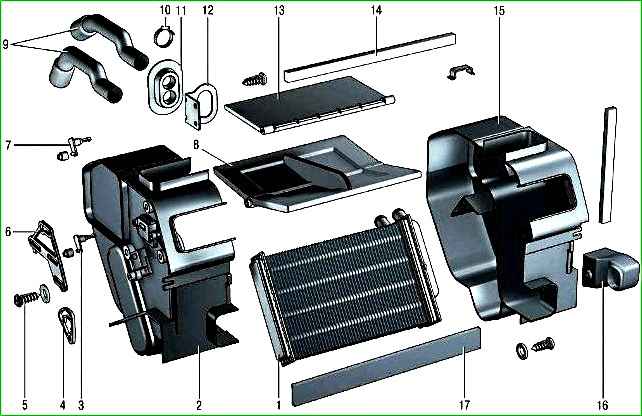
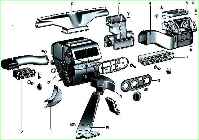
The vehicle is equipped with a liquid-type heater 12 (Fig. 1), combined with the engine cooling system
The heater radiator 1 (Fig. 2) is placed in a plastic casing installed in the central part of the instrument panel
A special feature of the heater is the absence of a tap. The heater is controlled by flaps 8 and 13.
The car can be equipped with either a heating and ventilation system or a heating, ventilation and air conditioning system.
These systems are designed to provide the most comfortable conditions for the driver and passengers, regardless of weather conditions.
The heating and ventilation system includes an outside air filter, a heater, a heater fan, air ducts and deflectors.
The air ducts supply air from the heater to the windshield and side window blower deflectors, to the central and side deflectors on the instrument panel, to the ventilation openings in the heater casing to supply air to the feet of the driver and passengers, and also to the feet of the rear seat passengers.
The heating and ventilation system is controlled by turning the handles of the control unit, which is installed on the central console of the instrument panel.
The heater housing is installed in the center under the instrument panel, on the right The heater fan housing is located near the front pillar behind the glove compartment.

The heating system is liquid, combined with the engine cooling system.
The heater radiator is installed in the instrument panel console in a plastic casing and sealed around the perimeter with foam tape.
Air heating depends on the degree of opening of the valve regulating the flow of liquid through the radiator. The valve is installed at the entrance to the radiator and is controlled by the upper lever on the center console.
The fan and the heater are connected to each other by intermediate air ducts.
Outside air for ventilation of the passenger compartment when the car is moving enters the car through the slots of the air intake under the windshield and the filter for cleaning the outside air (cabin filter).
To improve air circulation in the passenger compartment when driving, you can lower the door windows, and at low speed - turn on the electric fan of the heater.
In this case, you should move the temperature control handle to the cold (blue) zone, when the outside air enters the passenger compartment, bypassing the heater radiator.
Air flows in the passenger compartment are distributed by air ducts, which are located under the instrument panel and under the lining of the floor tunnel, and for supplying air to the feet of the rear passengers - and under the floor upholstery.
The control handle is used to control the distribution of air flows distribution on the central console of the instrument panel, as well as the controls and guides of the central and side deflectors on the instrument panel.
To heat the passenger compartment, move the temperature control handle to the hot (red) zone.
In this case, the outside air is directed through the heater radiator, which is combined with the engine cooling system, using a damper.
The heater radiator is installed in a corresponding housing and sealed along the perimeter with foam tape.

The ME-255 fan electric motor is a collector, direct current, with excitation from permanent magnets.
The fan speed is controlled by a three-position switch on the instrument panel.
Depending on the selected speed, the electric motor is connected to the vehicle's on-board network directly (high frequency) or through an additional resistor (low frequency).
The speed of rotation of the electric motor shaft with the impeller pat a voltage of 12 V and an air temperature of 25±10°C — 3000±150 min -1.
The current consumption at maximum rotation speed is no more than 4.5 A.
The fan impeller is fixed on the electric motor shaft. The electric motor cannot be repaired; if it fails, it is replaced.
The air is heated by the heat of the engine coolant circulating through the heater radiator tubes.
By turning the temperature control knob, you can change the position of the guide flap, thus regulating the volume of air passing through the heater radiator.
The air temperature control knob is located on the central console of the instrument panel.
The intensity of air supply is determined not only by the degree of opening of the outside air supply flap, but also by the speed of rotation of the fan impeller, which is changed by turning the fan speed control knob.
The speed control knob is located on the central console of the instrument panel. The fan motor can operate at four different speeds.
The air flow in the passenger compartment is directed by the air flow distribution handle, which is connected to the flaps by rods.
By controlling the flaps, you can direct the air flow through the air ducts to the central and side deflectors on the instrument panel, to the lower ventilation openings in the heater casing, as well as to the glass defroster grilles located in the instrument panel.
Some cars are additionally equipped with an air conditioning system, which is designed to reduce the temperature and humidity of the air in the passenger compartment.
The air conditioning system is turned on by pressing the air conditioner switch button located on the instrument panel panel, while the indicator located in the switch button lights up.
Before turning on the air conditioning system, it is necessary to turn on the heater fan and move the temperature control handle to the left, to the blue sector
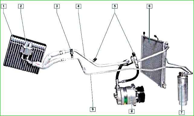
Large Some of the air conditioning system components are located in the engine compartment.
The only part of the vehicle interior is the evaporator, located under the instrument panel in place of the intermediate air ducts between the heater and its fan.

The evaporator serves for heat exchange between the air entering the car interior and the refrigerant circulating in the air conditioning system.
As it moves through the evaporator tubes, the refrigerant turns into steam.
The process is accompanied by heat absorption, the evaporator fins are cooled, the cold is removed from the fins and directed into the interior with the help of the heater fan, helping to lower the interior temperature in the interior.
The refrigerant, which is in a gaseous state, under low pressure enters from the evaporator into the compressor, which increases the pressure of the refrigerant.
The air conditioning compressor is installed on the right side of the engine cylinder block under the engine cooling system pump.
The compressor is driven by a poly V-belt from the accessory drive pulley.
In the pulley The compressor has a built-in electromagnetic clutch that engages and disengages the compressor shaft from the pulley based on signals from the engine management system controller.
The refrigerant vapors from the compressor under high pressure enter the condenser, which is located in front of the radiator of the engine cooling system.
Passing through the honeycombs of the condenser, the refrigerant is cooled by the oncoming air flow and by the fans of the cooling system. In this case, the refrigerant changes from a gaseous state to a liquid one.
Then the liquid refrigerant under high pressure enters the receiver, which is fixed under the right headlight in the cavity formed by the right wing, mudguard, front bumper and right mudguard of the bumper.
The receiver simultaneously performs several functions: as a filter, it cleans the refrigerant from impurities that have entered it; as a desiccant, it absorbs moisture condensing inside the air conditioning system and also serves as a reservoir for the refrigerant.
From the receiver, the refrigerant enters the reducer, located directly on the evaporator.
The reducer is a throttle valve, at the outlet of which the pressure and temperature of the refrigerant decrease sharply, as a result of which the refrigerant changes from a liquid to a gaseous state.
In this form, the refrigerant again passes through the evaporator, cooling the air entering the car interior.
From the evaporator, the refrigerant is sucked back into the compressor, and the working cycle is repeated.
Valves for filling and releasing refrigerant from the air conditioning system are installed on the high-pressure and low-pressure pipelines.
A refrigerant pressure sensor is installed on the high-pressure pipeline.
The pressure sensor sends a signal to the controller, which controls the electric fans of the engine cooling system depending on the refrigerant pressure and the vehicle speed.
In addition, based on the signals from the pressure sensor, the controller turns off the air conditioning compressor if the refrigerant pressure in the system is too low or too high.
A shut-off valve is installed under the pressure sensor in the fitting, which closes when the sensor is unscrewed, so when replacing the pressure sensor, refrigerant will not leak from the air conditioning system.
The refrigerant in the air conditioning system is mostly under high pressure.
During work related to with depressurization of the air conditioning system, avoid contact with eyes, skin and respiratory tract.
Any work with refrigerant must be carried out only in a ventilated area.
When filling the air conditioning system, use only materials recommended by the manufacturer.
Welding or soldering work on air conditioning system units is prohibited.
Repair and maintenance work on the air conditioning system should be carried out at specialized service centers.
Special equipment is used to search for leaks in the system, and a special contrast agent must be introduced into the system.
After removing the refrigerant from the system, it is imperative to pump out the air to remove residual moisture.
Before filling, a special oil recommended by the manufacturer must be added to the air conditioning system.


