Applies to engines without hydraulic compensators
To compensate for thermal expansion of the valve stem, a gap is required between the camshaft cam and the valve tappet
The gap between the camshaft cams and shims should be 0.20 mm for intake valves and 0.35 mm for exhaust valves
The gap is set by selecting the thickness of the adjusting washers.

The washers are installed in a niche located on the top of the pushers.
To make it more convenient to remove the washers, grooves are made on the upper edges of the pushers.
We measure and adjust clearances on a cold engine.
Remove the engine screen.

Use a Phillips screwdriver to loosen the clamp securing the crankcase ventilation hose

Remove the hose from the cylinder head cover pipe

Using a Phillips screwdriver, loosen the clamp securing the hose of the main circuit of the crankcase ventilation system

Remove the hose from the cylinder head cover

Loosen the clamp and remove the hose of the idle circuit of the crankcase ventilation system and remove the hose from the cylinder head cover pipe

Using a 10mm socket, unscrew the three nuts securing the receiver bracket

Remove the bracket

Two studs securing the bracket to the receiver are screwed into cage nuts installed in the grooves of the receiver

Using a 10mm socket, unscrew the two cap nuts securing the cylinder head cover

Remove the metal washer from the stud

And remove the rubber bushing

Remove the cylinder head cover
Counting from the camshaft drive, the first, fourth, fifth and eighth valves are exhaust valves; the second, third, sixth and seventh are inlet.
Remove the front timing belt cover (see "How to check and replace the Lada Kalina timing belt").
The procedure for checking and adjusting the clearances in the valve drive mechanism is as follows.
Table
The angle of rotation of the crankshaft from the position of the marks alignment (degree) - cam numbers
- 40-50 - first outlet 0.35 mm - third inlet 0.20 mm;
- 220-230 - release main fifth 0.35 mm - second inlet 0.20 mm;
- 400-410 - exhaust eighth 0.35 mm - inlet sixth 0.20 mm;
- 580-590 - fourth exhaust 0.35 mm - seventh inlet 0.20 mm
The clearance tolerance for all jaws is ±0.05 mm
The gap is equal to the thickness of the feeler gauge, which fits between the cams and the washer with slight pinching
Turn the crankshaft by the generator drive pulley bolt clockwise until the alignment marks on the camshaft pulley and the rear timing belt cover align.
Then turn the crankshaft clockwise another 40-50° (2.5-3 teeth on the camshaft pulley).

In this position of the shafts, use a set of feeler gauges to check the gaps at the first and third camshaft cams.
The clearance between the camshaft cams and shims should be 0.20 mm for the intake valves and 0.35 mm for the exhaust valves.
The clearance tolerance for all jaws is 0.05 mm.

If the gap differs from the norm, then install a device for adjusting the valves on the studs of the camshaft bearing housings.

We turn the pusher so that the slot in its upper part faces forward (along the direction of the car).
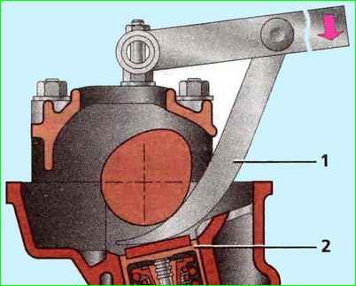
Insert the “fang” of the device between the cam and the pusher.

Press down on the lever of the device, recess the pusher with the “fang”.

We install a clamp between the edge of the pusher and the camshaft, which holds the pusher in the lower position.
Move the device lever to the upper position.

Use tweezers to pry the adjusting washer through the slot and remove it.

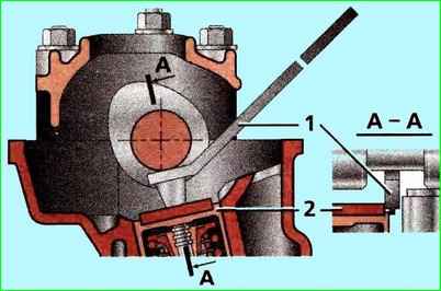
If you do not have a device for adjusting the valves, you can use two screwdrivers.
Using a powerful screwdriver, leaning on the cam, press the pusher down.
Inserting the edge of another screwdriver (with a blade width of at least 10 mm) between the edge of the pusher and the camshaft, fix the pusher and remove the adjusting washer with tweezers.

The gap is adjusted by selecting an adjusting washer with the required thickness.
To do this, use a micrometer to measure the thickness of the removed washer.
The thickness of the new adjusting washer is determined by the formula:
- H = B+(A-C), mm,
- where “A” is the measured gap; “B” is the thickness of the removed washer;
- "C" - nominal gap; “H” is the thickness of the new washer.
The thickness of the new washer is marked on its surface with an electrograph.
Insert the new washer into the pusher with the marking down and remove the lock.

Check the gap again. When adjusted correctly, a 0.20 or 0.35 mm feeler gauge should fit into the gap with slight pinching.
Successively turning the crankshaft half a turn, we check and, if necessary, adjust the clearances of other valves in the sequence indicated in the table.
Assemble the engine in reverse order.

Before installing the head cover, replace its gasket with a new one.
")

")
")
")
")
")
")
")