Usually the ignition switch is removed to replace it, as well as to replace the contact group of the switch or the APS coil
To check the ignition switch, sequentially set the key to the positions at which the circuits indicated in the table should be closed
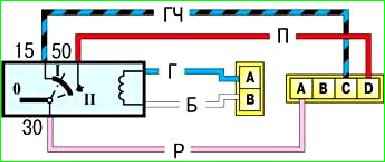
When the key is set to position “III”, the anti-theft device should turn on.
When the key is turned from position “III” to position “0”, the anti-theft device should turn off.
This can be checked by turning the steering wheel.
When starting again from position “I” to position “II”, the locking is activated.
The key can only be turned to position “II” from position “0”.
If there are defects, replace the contact group or ignition switch.
You will need: hammer, chisel, flat-blade screwdriver.
First of all, disconnect the negative terminal from the battery.
Remove the steering column switches.
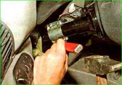
Ignition switch mounting bolts with cut heads.
Therefore, we unscrew them with a chisel.
As soon as the bolts are loosened, they can be unscrewed using pliers.
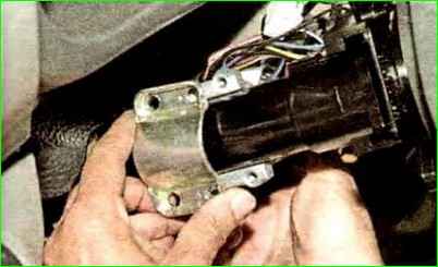
Remove the bracket from the steering column
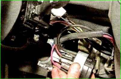
Remove the ignition switch
Use a screwdriver to pry up the clamp of the APS coil wire block
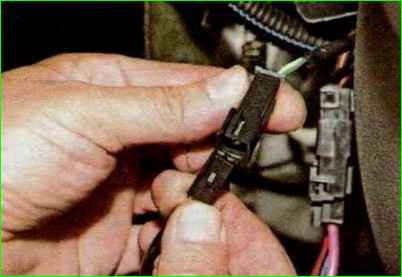
Disconnect the coil wire block from the APS block wire block
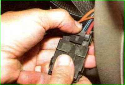
Press the connector lock and disconnect the ignition switch contact block from the wiring harness block
Remove the anti-theft locking rod
Turn the key in the ignition switch
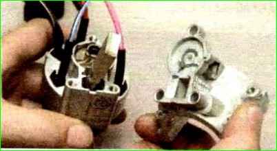
Remove the locking rod drive. Remove the rod spring from the drive
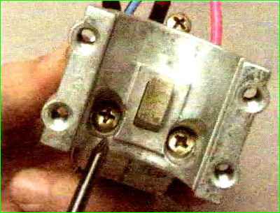
Remove the stopper with the spring
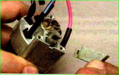
Push the cylinder out of the switch body
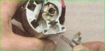
Take out the locking ball.
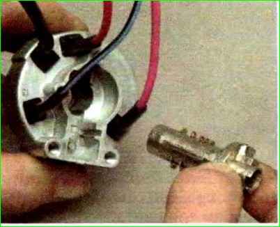
Remove the cylinder from the switch body
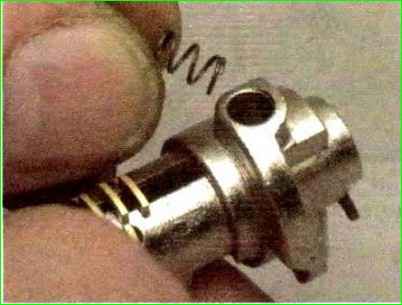
Remove the locking ball spring from the hole in the cylinder
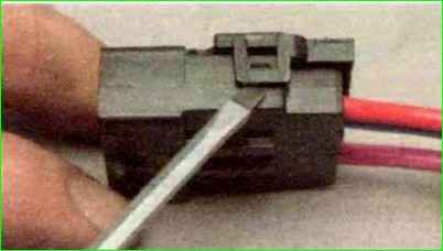
Use a screwdriver and disengage the two plastic latches of the wire block cover
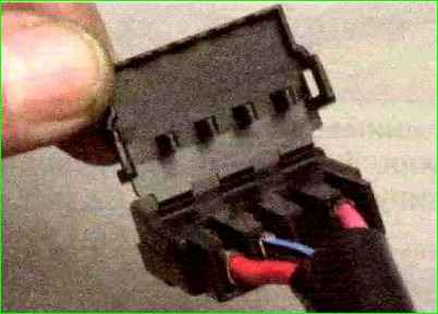
Open the connector cover.
Mark the wires located in the block
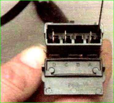
Use an awl to bend the locking tendrils of the wire lugs
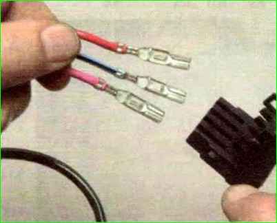
Remove the wires from the connector
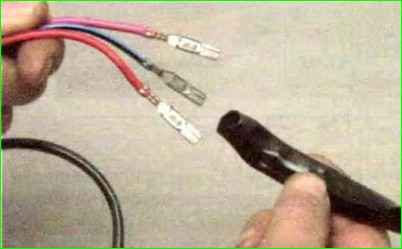
Remove the insulating tube from the wires
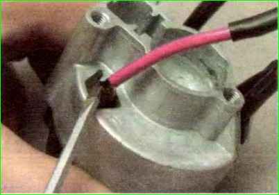
Use a screwdriver to squeeze the three plastic latches and remove the contact group from the body
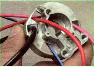
We bring out the wires through the holes in the housing
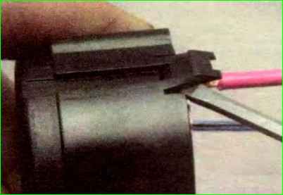
Use a screwdriver to disengage the three plastic latches
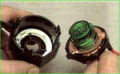
Disconnect the contact group
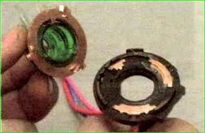
Remove the moving part of the contact group
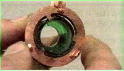
Press the moving contact and turn it counterclockwise
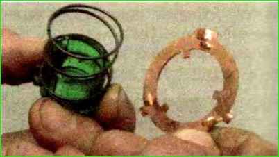
Remove the moving contact from the body
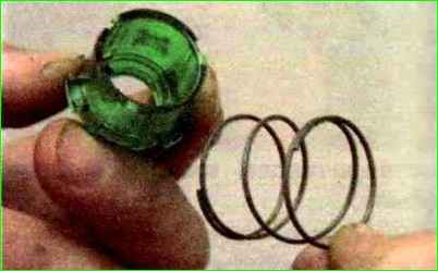
Remove the contact spring
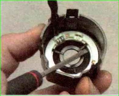
Pry up the APS coil with a screwdriver
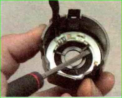
Remove the APS coil.
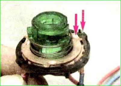
Assembly is carried out in reverse order
We install the moving part of the contact group so that the wide protrusion of the movable contact is located opposite the protrusion on the cover with the fixed contact
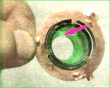
The protrusion on the lock cylinder should fit into the recess on the body of the moving part of the contact group
Table
Key position - Live contacts - Switched circuits
- “0”–off - 30 and 30/1 —
- “I”–ignition - 30–INT - External lighting. Instrument lighting. High beam headlight alarm
- 30/1–15/1 - Generator excitation winding. Ignition system. Windshield cleaner. Direction indicators. Reversing light. Control devices
- 30/1–15/2 - Low and high beam headlights. Fog light. Headlight cleaners. Rear window cleaner. Heated rear window. Washer. Heater fan. Engine cooling fan
- “II”–starter - 30–INT - See position I
- 30/1–15/1 - See position I
- 30–50 - Starter
- “III”–parking - 30–INT - See position I
- 30/1–P - Parking light


