Mechanism for raising and lowering the platform of KamAZ-5511 and KamAZ-55102 dump trucks
Additional equipment of dump trucks includes a mechanism for raising and lowering the platform, which ensures the raising and lowering of the platform;
- stopping it in any intermediate position during the process of lifting or lowering; automatic limitation of the maximum lift angle and pressure in the hydraulic system.
Control of the mechanism for raising and lowering the platform is electro-pneumatic, remote, carried out from the driver’s cabin by switches installed on the instrument panel.
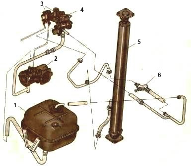
The hydraulic lifting mechanism (Fig.) consists of a power take-off box 2 with an oil pump, a hydraulic cylinder 5 of a control valve 4, a platform lift limiting valve 6, electro-pneumatic valves 3, an oil tank 1 with a filter and a system of pneumatic and hydraulic lines.
In addition to the specified standardized components, the platform lifting mechanism of the KamAZ-55102 dump truck has a locking device designed to connect the hydraulic system of the tractor with the hydraulic system of the trailer, and a hydraulic distributor that can direct the flow of oil to the hydraulic cylinder of the trailer.
The distributor is attached to the control valve.
Operating principle
The sequence of operations when raising and lowering the platform of a dump truck:
- to turn on the power take-off, disengage the clutch and place the switch in the “On” position (the warning lamp will light up).
The current through the thermobimetallic fuse is supplied to the winding of the electromagnet of the pneumatic valve, the core of which, moving, opens the valve.
Air from the receiver enters the cavity of the pneumatic chamber of the power take-off.
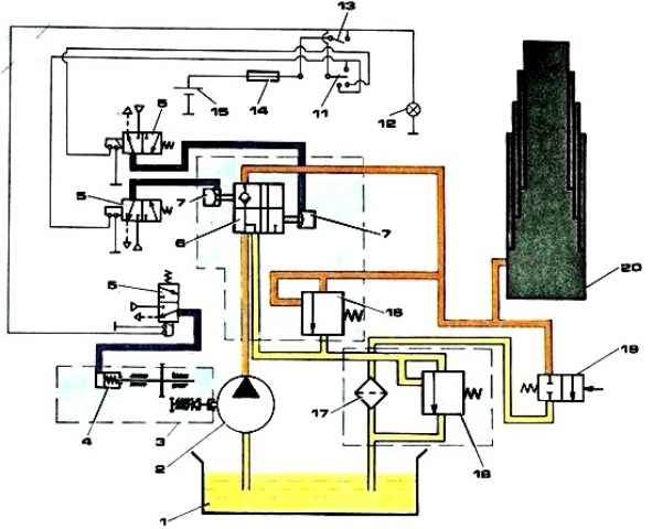
Diagram of the platform lifting mechanism of the KamAZ-5511 vehicle: 1 – oil tank; 2 – oil pump; 3 – power take-off (PTO); 4 – pneumatic chamber; 5 – electro-pneumatic valve; 6 – control valve; 7 – pneumatic chamber; 8 – distribution valve; 9 – control lamp; 10 – hydraulic system distributor switch for tractor or trailer; 11 – switch for the platform raising and lowering mechanism; 12 – control lamp for switching on “COM”; 13 – “COM” switch; 14 – fuse; 15 – 24 V current source; 16 – hydraulic system safety valve; 17 – filter; 18 – filter safety valve; 19 – platform lift limitation valve; 20 – tractor hydraulic cylinder; 21 – trailer hydraulic cylinder
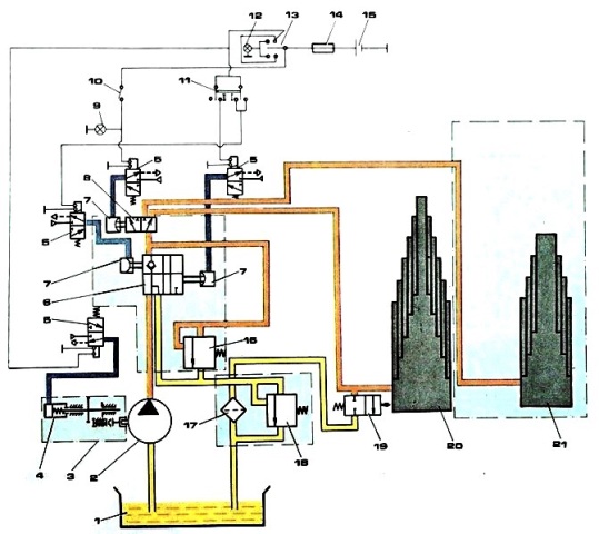
Diagram of the platform lifting mechanism of the KamAZ-55102 vehicle: 1 – oil tank; 2 – oil pump; 3 – power take-off (PTO); 4 – pneumatic chamber; 5 – electro-pneumatic valve; 6 – control valve; 7 – pneumatic chamber; 8 – distribution valve; 9 – control lamp; 10 – hydraulic system distributor switch for tractor or trailer; 11 – switch for the platform raising and lowering mechanism; 12 – control lamp for switching on “COM”; 13 – “COM” switch; 14 – fuse; 15 – 24 V current source; 16 – hydraulic system safety valve; 17 – filter; 18 – filter safety valve; 19 – platform lift limitation valve; 20 – tractor hydraulic cylinder; 21 – trailer hydraulic cylinder
When the clutch is engaged, the oil pump will start working. Oil from the tank, through the suction and discharge cavities of the pump, flows through a pipeline into the control valve, and then drains into the tank. Such oil circulation helps to warm it up in winter, which improves the operating conditions of the hydraulic system of the tipping mechanism;
- to raise the platform, move the switch to position “II”. In this case, the current passes through the windings of electro-pneumatic valves, the cores of which, moving, open the valves.
Air from the receiver is supplied to the pneumatic chambers of the control valve. Oil from the control valve flows through pipelines into the hydraulic cylinder.
Under the influence of oil pressure, the hydraulic cylinder links sequentially extend, raising the platform.
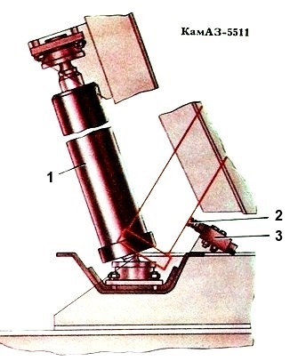
As the platform rises, the hydraulic cylinder tilts; When the maximum lift angle is reached, the hydraulic cylinder body presses the adjuster tighten the platform lift limit valve screw, and the oil is drained through the valve into the tank. The platform lifting stops;
- to stop the platform in an intermediate position during the process of raising or lowering, move the switch to the neutral position.
In this case, the electro-pneumatic valves are turned off, the air leaves the working cavities of the pneumatic chambers into the atmosphere.
The hydraulic cylinder line is closed, and the cavity of the control valve communicates with the drain line, and the oil from the pump is drained through the control valve into the tank;
- to lower the platform, move the switch to position I. The current flows to the winding of the electro-pneumatic valve “I”, the core of which, moving, opens the valve.
Air from the receiver enters pneumatic chamber “a” of the control valve. Through the control valve, oil is drained from the hydraulic cylinder into the tank.
After the platform has been lowered, it is necessary to set the switch to the “Off” position (after disengaging the clutch). In this case, the oil pump stops working.
Regulation
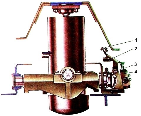
Check the condition and correct adjustment of the platform lift limit valve (see figure). The valve must be securely fastened to the subframe cross member bracket.
The adjusting screw must be locked with a locknut. Do not allow the valve stem to be bent or oil to leak from under the stem seal or through the threaded connections of the pipelines.
When the platform lift angle is correctly adjusted, the locking pins (Fig.) of the platform should freely fit into the holes in the subframe brackets. Do not operate the vehicle if the platform lift angle is not adjusted properly.
To adjust the lifting angle of the dump truck platform:
- - unscrew the lock nut (see figure) of the adjusting screw;
- - screw the adjusting screw into the rod until it stops;
- - lift the platform to a position where the platform locking pins fit freely into the holes in the subframe brackets, and lock the platform in this position with the locking pins;
- - unscrew the adjusting screw from the valve stem until it touches the hydraulic cylinder body and lock it with a lock nut.
- - unlock the platform, lower it and raise it again.
make sure that the lifting stops when the axis of the locking pins 3 (Fig.) coincides with the axes of the holes in the subframe brackets.
The deflection of the safety cable should be 35 - 50 mm. If the deflection is different, adjust the length of the cable by loosening the cable clamps.
Checking the oil level and filling the hydraulic system
Check the oil level in the tank with the platform down using the indicator mounted in the tank lid. The level should be located between the “H” and “B” marks on the indicator.
To refuel the hydraulic system:
- - unscrew the oil tank filler cap, remove, wash and reinstall the strainer;
- - fill the oil to the “B” mark marked on the oil level indicator;
- - raise and lower the platform 3-4 times at an average engine speed (1100 - 1300 min -1) to pump the system and remove air from it;
- - check the oil level, if necessary, add to the “B” mark.