Removal and installation of the GAZ-3110 steering column
Disconnect the wire from the negative terminal of the battery.
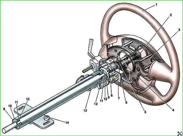
Remove the steering wheel
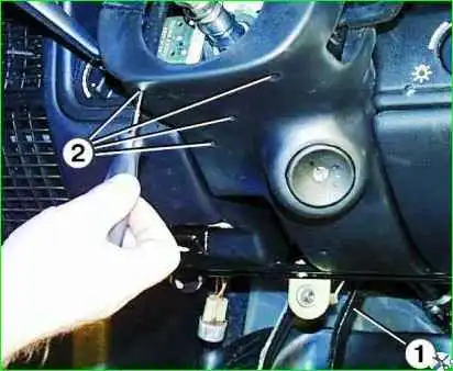
Unscrew the two fastening bolts and remove amplifier 1 of the instrument panel with the socket for carrying installed on it.
Unscrew one screw securing the upper casing, four screws 2 securing the lower casing of the steering column and remove both casings
Disconnect the block with the ignition switch wires.
Unscrew the three fastening screws 1 and remove the base 2 with the steering column switches assembly.
The base with the steering column switches can be put aside without disconnecting the wires from the switches.
If the length of the harnesses is not enough to remove the base with the steering column switches as an assembly from the steering column, then you can unscrew two screws securing both steering column switches and disconnect them from the base.
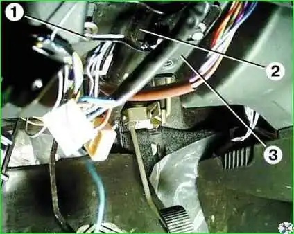
Unscrew the two bolts 1 securing the steering column to the bracket.
Lower the steering column and remove the bushings installed between the steering column 2 and bracket 3.
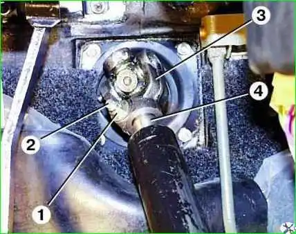
Unscrew the fastening nut 1, remove the wedge 2 and disconnect the steering column shaft 4 from the universal joint 3.
Remove the steering column from the car
Disassembling the steering column
Set the ignition switch to position “0” using the key, thereby disabling the anti-theft device.
Clamp the steering column in a vice by the eyes of the steering column pipe.
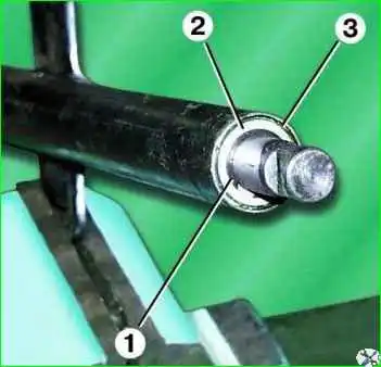
Remove lock rings 1, washers 2 and bushings 3 from both ends of the steering column shaft.
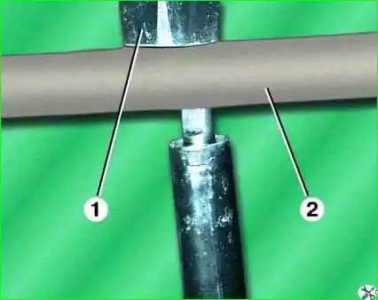
Press the steering column shaft out of the pipe by hitting the lower end of the shaft with a hammer 1 through a wooden mandrel 2
Remove the upper steering column bearing from the shaft, and remove the lower one from the pipe.
If necessary, unscrew the two fastening bolts and remove the ignition switch with the anti-theft device assembly.
Inspection of steering column parts
Set the ignition switch to position “0” using the key, thereby disabling the anti-theft device.
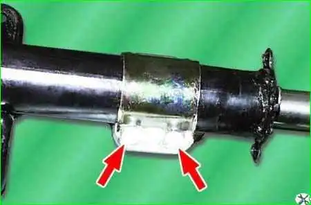
Clamp the steering column in a vice by the eyes of the steering column pipe.
Remove retaining rings 1, washers 2 and bushings 3 from both ends of the steering column shaft.
Press the steering column shaft out of the pipe by hitting the lower end of the shaft with a hammer 1 through a wooden mandrel 2.
Remove the upper steering column bearing from the shaft, and remove the lower one from the pipe.
The steering column is assembled in the reverse order of disassembly.
Installing the steering column
Install the steering column in the reverse order of removal.
Do not forget to install bushings between the steering column mounting eyes and the bracket.
Tightening torques for threaded connections attaching the steering column to the bracket are 12–18 Nm (1.2–1.8 kgf m), nuts securing the universal joint fork are 18–25 Nm (1.8–2.5 kgf m ).
If necessary, unscrew the two fastening bolts and remove the ignition switch with the anti-theft device assembly.


