Unscrew the oil drain plug and drain the oil from the main gear housing
Unscrew the four bolts securing the rear propeller shaft to the rear axle drive gear flange and move the rear propeller shaft to the side.

Remove both axle shafts.

Unscrew the ten mounting bolts and remove the gearbox cover.

Remove cotter pin 1, unscrew fastening nut 2 and remove flange 3 from the splines of the drive gear.

Unscrew bolts 1 and remove locking plates 2 of adjusting nuts.
Mark 3 bearing caps, unscrew two bolts 4 fastenings on each side and remove the bearing caps.

Loosen the two adjusting nuts 1 located on each side of the differential.
Remove differential 3 with bearings and driven gear assembly and mark the outer and inner rings of bearings 2 so as not to confuse them during installation.

Remove drive gear 1. In this case, the front bearing of the drive gear shaft remains in the rear axle housing.

Remove the drive gear flange seal.
Remove the front bearing from the rear axle housing.
Press the outer rings of the outer and inner bearings of the drive gear shaft out of the crankcase.
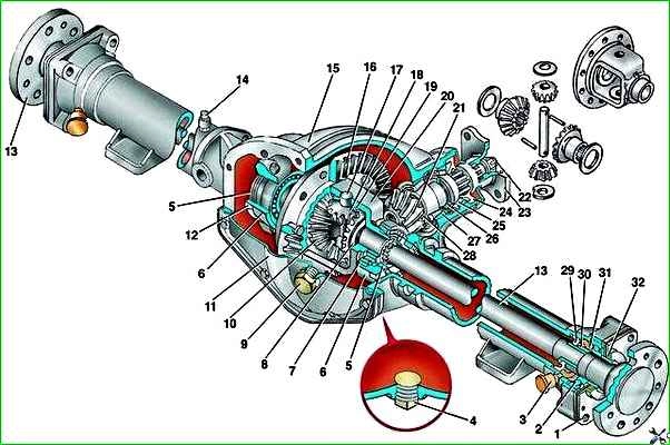
Disassembling the main gear drive shaft

Compress the inner race of the front bearing.

Remove spacer ring 1 of the front bearing.
Compress rear bearing 2 with the inner ring and remove the adjusting ring.
Disassembling the differential

Mark the relative positions of driven gear 1 and flange 2 of the differential box.
Unscrew the nuts of the 3 bolts securing the driven gear to the differential box and knock the bolts out of the sockets of the driven gear without damaging the threads.
Remove (compress) the driven gear from the differential box.

Use a thin hard rod to knock out the pinion axis stopper from the hole 2 of the differential box.
Knock axis 1 of the satellites out of the box.

Roll out the satellites 1 with washers, and then remove the semi-axial gears 2 with washers from their sockets. Press differential bearings 3.
It is recommended to wire the bearings to the corresponding outer rings.
Inspection and troubleshooting of main gear parts
Wash and dry the main gear parts.
Check remove the differential box. If cracks are found on the box, it must be replaced.
Check the final drive teeth. If they are chipped, chipped, or scored, both final drive gears must be replaced.
Inspect the side gears, satellites, axle and washers.
The semi-axial gears and satellites should not have broken teeth or signs of increased wear on the spherical surface.
The surface of the axle should be smooth and level and should not have steps in the places where the satellites fit.
If the washers are worn unevenly, they must be replaced.
The internal mating surfaces of the differential box must not show signs of wear.
Check for signs of wear on the surfaces of the bearing seats. Replace worn parts.
The bearings of the drive gear and differential box must be free of pitting, cavities and visible wear on the rolling surfaces.
Differential assembly
Press the main drive driven gear onto the differential box, aligning the previously made marks.
Insert ten bolts into the holes of the driven gear and tighten the fastening nuts with a torque of 68–75 Nm (6.8–7.5 kgf m).
Press roller bearings onto the seats of the differential box.

Insert the side gears with washers into the differential box.
Insert satellites with washers into the differential box windows, engaging them with the semi-axial gears.
Then rotate the satellites so that the holes for the axle on the differential box and satellites align.
Insert the satellite axle, aligning the holes in the box and the axle under the stopper.
Measure the axial clearance of the side gears using two feeler gauges.
With correctly selected washers, the gap should be in the range of 0.03–0.05 mm.
Insert the axle stopper and open the hole.
Adjusting the main gear of the GAZ-3110 according to the contact patch of the teeth
If at least one of the rear axle parts that affects the installation size has been replaced, then it is necessary to select an adjusting ring for the drive gear shaft.
Press the outer races of the drive gear shaft bearings into the rear axle housing.
Install the rear bearing on the drive gear shaft, insert the drive gear into the rear axle housing and install the front bearing.

Install the drive gear flange. Tighten the nut, turning the shaft by the flange so that the rolling elements of the bearings fall into place.
The nut is tightened so that the turning torque of the new bearings is 1.75–2.25 Nm (0.175–0.225 kgf m).

Measure distance “A” from the end of the drive gear to the rear end of the rear axle housing.
Install mandrel 1 with a length of 190 mm and a diameter of 90 -0.01 "lower limit" into the seats of the differential bearings.
Install the differential bearing caps and tighten the mounting bolts to a torque of 90–100 Nm (9.0–10.0 kgf·m).
Measure distance B from the mandrel to the rear end of the rear axle housing.
Calculate the size “M” from the end of the drive gear to the differential axis using the formula M = A – B – D/2, where
- A — distance “A” from the end of the drive gear to the rear end of the rear axle housing, mm;
- B — distance from the mandrel to the rear end of the rear axle housing, mm;
- D - mandrel diameter equal to 90 mm.
Calculate the thickness "T" of the adjusting ring as the difference between the actual dimension "M" and the installation dimension equal to 65 mm.
You should take into account the amount of correction “P” of the mounting size indicated on the end of the drive gear with the corresponding sign:
T = M – 65 – P, where
- M - size from the end of the drive gear to the differential axis, mm;
- P – correction value for installation size, mm.
It should be taken into account that the value of the correction “P” can have a “+” or “–” sign and must be substituted into the formula with its sign, i.e. when the correction value is with a “+” sign, it is subtracted, and with a “–” sign, it is added.
Select an adjusting ring from a repair kit of calculated thickness (T±0.02) mm from the 22 groups supplied as spare parts. The group number is indicated on the adjusting ring.
Remove the mandrel.
Remove the drive gear from the rear axle housing by unscrewing the fastening nut and removing the drive gear flange.
C press the rear bearing off the drive gear shaft, install the selected adjusting ring and press the rear bearing again.
Install the drive gear into the rear axle housing.
Select the front bearing preload spacer ring. The spacer ring is installed between the shaft shoulder and the inner ring of the front bearing.
The spare parts are supplied with 47 groups of spacer rings with a thickness of 4.05 to 5.43 mm every 0.03 mm.
Select a spacer ring so that the turning torque of the drive gear shaft bearings is 1.5–2.5 Nm (0.15–0.25 kgf m) with the flange installed and the nut tightened to a torque of 160–200 Nm ( 16–20 kgf m).
When tightening the nut, it is necessary to turn the shaft by the flange so that the rolling elements of the bearings fall into place.
After assembling the spacer ring, finally install the front bearing in place.
Lubricate the working edge of the drive gear flange oil seal and press it flush with the end of the crankcase.
Install the drive gear flange and tighten the nut securing it with a torque of 160–200 Nm (16–20 kgf m).
Install the cotter pin and check the torque of the bearings again.
Install the differential with bearings into the rear axle housing and insert the adjusting nuts into the threads so that they touch the bearings.
Install the bearing caps in accordance with the markings and tighten the bolts securing them so that the adjusting nuts rotate freely.
Install a stand with an indicator. In this case, the indicator leg should touch the tooth surface near the outer end of the driven gear and be directed radially towards the tooth surface.
Determine the amount of the resulting side clearance by selecting the gap between the main gear gears by turning a certain angle to one side of rotation of the driven gear until it stops and setting the indicator scale to zero.
Measure the amount of lateral clearance with an indicator, rocking the driven gear until it stops around the axis in both directions.
Carry out measurements at at least eight points of the gear equally spaced from each other.
At each measurement, it is recommended to block the drive gear from turning. The side clearance should be within 0.15–0.25 mm.
If the side clearance does not fall within these limits, you must use the adjusting nuts to move the gear in the required direction.

Adjust the differential bearings. To do this, install an indicator and, using adjusting nuts, set the axial clearance in the bearings to about 0.05 mm.
Then ensure the necessary preload of the bearings using adjusting nuts by the amount of the actually measured axial play, adding to this value 0.1 mm for bearings with a mileage of less than 10 thousand km and 0.05 mm for bearings with a mileage of more than 10 thousand km .
In this case, turning one adjusting nut relative to the other by one groove corresponds to moving along the axis by 0.03 mm.

Check again and, if necessary, adjust the side clearance.
To reduce the gap, the nut on the side of the driven gear must be tightened and at the same time loosen the opposite nut by the same number of grooves; to increase the gap, the actions are exactly the opposite.
In this case, it is always necessary to loosen the nuts one notch more than required, and then tighten them by one notch.
Finally tighten the differential bearing cap bolts to a torque of 90–100 Nm (9–11 kgf m).
Check the side clearance again and adjust if necessary.
You can also adjust the engagement of the main gears by the contact pattern of the gear teeth.
This method is more labor-intensive, but at the same time you can get the best result of meshing the final drive gears.
Install the locking plates of the adjusting nuts and tighten the bolts from the fastening.
Calculate the thickness of adjusting ring 1 and install the drive gear together with the selected ring in the crankcase.
In this case, the spacer ring 26 is selected only after the final installation of the main drive gears.
Install the differential with the driven gear and adjust the differential bearings.
Apply a thin coat of long-drying, thick primer to all drive gear teeth.

Rotate the drive gear one turn in both directions.

Carefully inspect all drive gear teeth on both sides. Where the gears contact, the primer will be erased.
Carefully inspect all drive gear teeth on both sides. Where the gears contact, the primer will be erased.
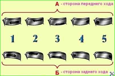
When adjusting the gear mesh correctly, the contact patch should be located in the center of the drive gear tooth.
If the contact patch is located on the upper edge of the tooth, it is necessary to move the drive gear towards the driven gear. To do this, you need to select and install an adjusting ring 28 of greater thickness.
If the contact patch is located at the base of the tooth, then it is necessary to move the drive gear away from the driven gear. To do this, you need to select and install an adjusting washer 1 of smaller thickness.
If the contact patch is located at the front end of the tooth, then it is necessary to move the driven gear away from the drive gear.
To do this, adjusting nut 5 on the side of the driven gear must be unscrewed to the required number of grooves and at the same time tighten the opposite nut by the same number of grooves.
In this case, it is always necessary to unscrew the nut one notch more than required, and then tighten it by one notch.
If the contact patch is located at the rear end of the tooth, then it is necessary to move the driven gear towards the driving gear.
To do this, adjusting nut 5 on the side of the driven gear must be tightened to the required number of grooves and at the same time unscrew the opposite nut by the same number of grooves.
In this case, it is always necessary to unscrew the nut one notch more than required, and then tighten it by one notch.
Due to inaccuracy in the manufacture of gears, the contact patch on different teeth may “walk.”
Therefore, it is necessary to align the gears so that the contact pattern on all teeth approaches the correct position.
Repeat step 30 until the required result is obtained. At the same time, during each inspection it is necessary to restore the soil layer on the teeth.
After adjustment, finally assemble the rear axle.
Pour 1.65 liters of transmission oil into the main gear housing through the filler hole.
")

")
")
")
")
")
")
")