Removal and installation of connecting rods and pistons of the ZMZ-402 engine
Remove the cylinder head, article - "Cylinder head ZMZ-402 GAZ-3110"
Remove the oil pump.
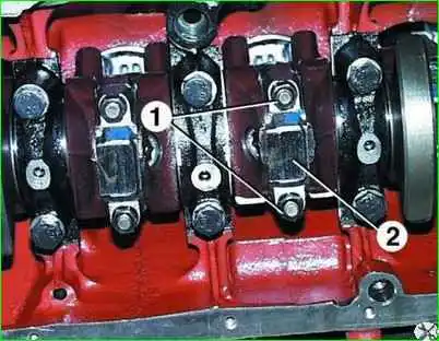
Unscrew the nuts 1 of the connecting rod bolts and remove the connecting rod cover 2.
Since the lid is tightly seated, knock it off with gentle blows of a hammer.
Remove the connecting rod bearing shell from the cover.

Push the piston into the cylinder until it comes out of the cylinder, and then remove it along with the connecting rod.
Remove the connecting rod bearing shell from the lower head of the connecting rod.
Remove the piston and connecting rod from the cylinder carefully so as not to damage the cylinder bore.
Check the marks on the connecting rod and connecting rod cap. If the marks are not visible, mark the connecting rod and cap with the cylinder number.
In the same way, remove the remaining pistons and connecting rods.
Use a puller to remove the piston rings.

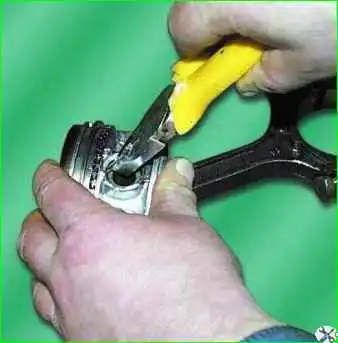
Remove the retaining rings on both sides of the piston.

Press out the piston pins using a special tool.
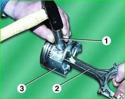
If there is no device, you can knock out the piston pins with light blows of a hammer through mandrel 1 - this must be done in weight so as not to damage the piston. Remove connecting rod 2 from piston 3.
In the same way, remove the remaining pistons from the connecting rods.
After disassembly, wash all parts in gasoline. Clean the pistons from carbon deposits.
Clean the piston ring grooves with an old piston ring or a broken ring.
Inspection of connecting rods and pistons
Inspection, testing and repair of parts of the connecting rod and piston group are carried out similarly to operations on the engine mod. 406. Differences are shown below.
The gap between the oil scraper piston ring and the groove on the piston should be in the range of 0.135–0.335 mm.
The gaps in the piston ring locks should be in the range of 0.3–0.7 mm for compression rings and 0.3–1.0 mm for oil scraper rings.
Fingers and connecting rods are marked with paint: pin in the hole, connecting rod on the rod near the upper head.
A Roman numeral is stamped on the bottom of the piston, indicating the piston group.
The pin should not fall out of the connecting rod head if it is tilted at approximately 45°.
The difference in weight between pistons assembled with connecting rods, pins, and piston rings installed on one engine must be no more than 12 g.
Assembly and installation
Assembly and installation of the connecting rod and piston group are similar to those on the engine mod. 406.
When installing the connecting rod bolt nuts, seal them with Unigerm-9 sealant.


