Removal and installation of the ZMZ-402 cylinder head of the GAZ-3110
The cylinder head can be removed with the intake pipe and exhaust manifold. If the cylinder head is removed from an engine installed on a car, you must first perform the following operations:
- drain the liquid from the cooling system;

- remove the air filter from the carburetor;

- disconnect the hoses from the thermostat;


- - disconnect the wire from the coolant temperature sensor;
- - disconnect the wires from the microswitch on the carburetor;
- - disconnect the choke rod and the accelerator drive rod from the carburetor;
- - disconnect the fuel drain hose from the carburetor;
- - disconnect the hoses from the EPHH solenoid valve installed on the front panel;
- - disconnect the brake booster vacuum hose from the fitting on the intake pipe;

- disconnect the heater outlet hose from the fitting on the rear cover of the cylinder head or heater tap
Then the procedure for removing the cylinder head from an engine removed from a car and from one installed on a car is the same.
Remove the tips with wires from the spark plugs and unscrew spark plugs 1. Disconnect hose 3 from the fine fuel filter.
Disconnect the vacuum hose 2 of the ignition distributor vacuum corrector from the carburetor.

Disconnect hose 3 for crankcase ventilation from the pipe on the rocker cover.
Unscrew the six bolts 1 and remove the rocker arm cover 2 along with the gasket.

Unscrew nuts 1 and remove axle 2 with valve rocker arms and struts assemblies. Remove the 4 valve lifter rods.
Unscrew nuts 3 and remove block head 5 and head gasket.
It is not recommended to drive a screwdriver or any other tool between the cylinder head and the cylinder block, as this may damage the surface of the cylinder head adjacent to the block or the surface of the cylinder block.
Secure the cylinder liners by placing wide washers on the head mounting studs so that they overlap adjacent liners.
Then put suitable sections of tubes on the studs and tighten them with the nuts securing the block head.
Disassembling the cylinder head

Unscrew nuts 1 and remove thermostat housing 2 with cover assembly.

Unscrew the six nuts 1 and remove the intake pipe 2 with the exhaust manifold 3 of the 1st and 4th cylinders

Unscrew nut 1 and remove exhaust manifold 2 of cylinders 2 and 3 from the cylinder head

Unscrew bolts 1 and remove cover 2 with gasket from the rear end of the cylinder head.

Mark the valves with the cylinder number so that when assembling the cylinder head, you can install them in their place.
Install a special device for compressing the valve springs on the cylinder head.

Compress the valve springs using a tool and remove the valve nuts 1. Then, gradually loosening the pressure on the handle of the device, completely release the valve springs.
Remove the device from the block head. Remove valve springs 3 with spring retainer 2.
Turn the cylinder head over and remove the valve from the combustion chamber side.
Remove the oil seals 1 from the valve guides and the support plates 2 of the valve springs
Remove cotter pins 1 and remove from axle 5 the rocker arms of the axle strut 3, the rocker arms 2 of the valves and the spacer spring 4.
There are cases when the cylinder head is poorly separated from the block. This usually happens due to oxidation of the aluminum head at the location where the studs are attached.
In this case, you need to use either kerosene or acetic acid.
Pour into the gap between the studs and the body and wait a while.
Then, by rocking, using the mounting tools, try to separate and push back to move the head.
You should never push screwdrivers or other tools between the block and the head, as this can damage the head.
You can also see the article on removing the cylinder head - “Replacing the cylinder head gasket”
Inspection of cylinder head parts
- 1. After disassembling the cylinder head, wash all parts in gasoline, wipe and dry. Clean the combustion chambers from carbon deposits.
- 2. Inspect the block head. If there are cracks on the bridges between the valve seats or on the walls of the combustion chambers, or signs of burnout, replace the cylinder head.
- 3. Using a metal ruler and feeler gauges, check to see if the flatness of the surface of the head adjacent to the block is broken.
To do this, place the ruler with its edge on the surface of the head, in the middle along, and then across, and use feeler gauges to measure the gap between the plane of the head and the ruler. If the gap exceeds 0.1 mm, replace the head.
- 4. Inspect the valves. If cracks, warping of the valve head, burnout, or deformation of the stem are detected on the working face of the valve, replace the valve. Minor marks and scratches on the working face of the valve can be removed by lapping.
- 5. Check the condition of the valve springs. Replace bent, broken or cracked springs.
- 6. Check the condition of the valve seats. There should be no signs of wear, holes, corrosion, etc. on the working chamfers of the seats. Minor damage (small marks, scratches, etc.) can be removed by grinding the valves.
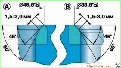
More significant defects are eliminated by grinding. When grinding, maintain the seat dimensions indicated in the figure.
After grinding, check the runout of the seat chamfer relative to the hole in the valve guide, the maximum permissible runout is 0.05 mm.
After grinding the seats, grind the valves. Then thoroughly clean the block head and blow it with compressed air so that there are no abrasive particles left in the channels closed by the valves and in the combustion chambers.
Check the gap between the guide bushings and the valves. The clearance is calculated as the difference between the diameter of the hole in the bushing and the diameter of the valve stem.
The maximum permissible gap is 0.25 mm. If the gap exceeds the specified value, the valve and guide sleeve must be replaced.
The old bushing is pressed out using a mandrel from the side of the combustion chamber.
Before installation, new bushings must be cooled in carbon dioxide (“dry ice”), and the block head must be heated to 160 - 175 °C.
Then insert the bushing into the cylinder head so that it protrudes from the valve spring side above the cylinder head by 20 mm.
The bushing should be inserted into the head freely or with little force.
After installation, expand the hole in the bushing to a diameter of 9.0+0.022 mm. Then grind the valve seat, centering the tool on the hole in the bushing.
You can check the block head for cracks as follows. Connect a compressed air hose to one of the holes in the cooling jacket.
Plug all holes I'm in the block head with wooden plugs. Lower the head into a bath of water and apply compressed air at a pressure of 1.5 atm.
Air bubbles will emerge where cracks form.
Clean with wire and blow out with compressed air the holes in the rocker arm axle, in the rocker arms and in the adjusting screws. Check the tightness of the bushings in the rocker arms.
If the bushing does not fit tightly, it needs to be replaced, since during engine operation it can turn and block the hole for supplying oil to the pusher rod.
Assembling the engine cylinder head
Assemble the block head in the reverse order of disassembly. Before installation, lubricate oil seals, valve stems and valve rocker shafts with engine oil.
Install the valves in accordance with the marks made during disassembly.
Install the gasket of the thermostat housing and the gasket of the rear cover of the block head with a Hermesil type sealant.
When installing the cylinder head, it is recommended to replace the cylinder head gasket.
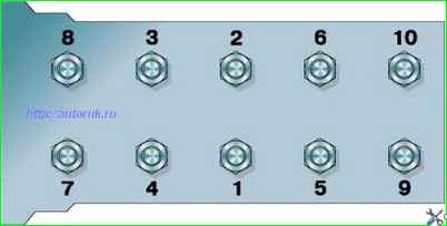
The cylinder head is installed in the reverse order of removal. The procedure for tightening the cylinder head bolts is shown in Fig.
Sequence of tightening the cylinder head bolts.
Tightening torque 83–90 Nm (8.3–9.0 kgf m). After installing the cylinder head, adjust the clearances in the valve drive.
Installing the cylinder head
Install the block head in the reverse order of removal.
Tighten the cylinder head mounting bolts in two stages:
- 1st stage - 40–60 Nm (4.0–6.0 kgcm);
- 2nd stage - 130–145 Nm (13.0–14.5 kgcm).
")

")
")
")
")
")
")
")