Brake light switch
The brake light switch is installed on the side of the brake pedal
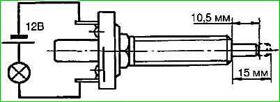
The serviceability of the switch can be checked using a test lamp according to the diagram in Fig. 1
When the switch rod protrudes by 15 mm, the control lamp should light up, and when you press the rod (protrusion 10.5 mm), the lamp should go out.
The voltage drop at the switch terminals should be no more than 0.1 V at a current of 6 A. Replace the faulty switch.
When installing a new switch, adjust its installation on the bracket.
The brake light warning lights should light up only after pedal free travel has been selected.
Reversing light switch
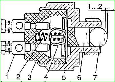
The reverse light switch (Fig. 2) is used to automatically turn on the light when reversing.
The switch is installed in the gearbox and is mechanically connected to the gear shift lever.
When the lever is in the appropriate position, the switch connects the reversing light circuit to the power source.
During operation, you should periodically check that the switch is securely fastened.
Checking the switch can be done using a test lamp.
The lamp should light up when the ball moves 1-2 mm. Replace the faulty switch.
Hazard switch
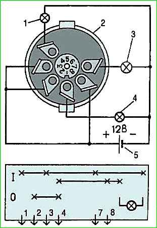
Hazard switch 24.3710 is checked according to the diagram in Fig. 3.
In the off position, lamp 1 should be lit, in the on position - 1, 3 and 4, as well as in the switch handle. If one of the lamps does not light in the corresponding position, replace the switch.
")

")
")
")
")
")
")
")