Engine lubrication system mod. 406 and 402 combined: under pressure and spray
The lubrication system consists of the engine oil sump, oil pump, full-flow filter, oil cooler, hoses and oil channels in the engine block
The pressure in the lubrication system is created by a gear oil pump.
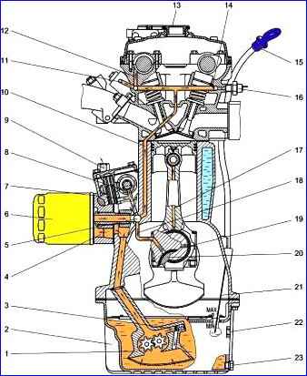
The oil pump takes oil from the engine crankcase and supplies it to the full-flow oil filter, then the oil passes through the channels to the main bearings and from them to the connecting rod bearings.
Oil flows through a channel in the connecting rod to the piston pin.
Part of the oil flows through a vertical channel into the cylinder head, where it lubricates the valve drive parts, and from there flows into the crankcase.
Part of the oil from the oil pump passes through the oil cooler valve and enters the oil cooler, where it cools and returns to the engine crankcase.
In the engine mod. 406 oil, in addition, passes through hydraulic chain tensioners and hydraulic valve lifters.
More details can be found in the article - "Lubrication system ZMZ-406 GAZ-2705"
")

")
")
")
")
")
")
")