The lubrication system is combined, with oil supplied to the rubbing surfaces under pressure and splashing and automatic control of the oil temperature by a thermal valve
Hydraulic valve lifters and chain tensioners are lubricated and perform their functions under oil pressure.
The lubrication system includes: oil sump, oil pump with inlet pipe and pressure reducing valve, oil pump drive, oil channels in the cylinder block, cylinder head and crankshaft, full-flow oil filter, oil level indicator rod, thermal valve, oil filler cap, oil drain plug and oil pressure sensors.
Oil circulation occurs as follows.
Pump 1 sucks oil from crankcase 2 and delivers it through the cylinder block channel to thermal valve 4.
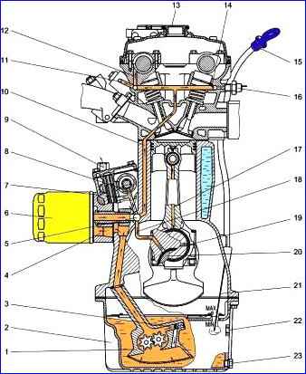
Lubrication system diagram: 1 - oil pump; 2 - oil sump; 3 - oil pump bypass valve; 4 - thermal valve; 5 - central oil line; 6 - oil filter; 7, 8, 10, 11, 12, 14, 17, 18, 19 - oil supply channels; 9 - fitting of the thermal valve for draining oil into the radiator; 13 - oil filler pipe cover; 15 - oil level indicator handle; 16 - emergency oil pressure indicator sensor; 20 - crankshaft; 21 oil level indicator rods; 22 - connection hole for the oil supply hose from the radiator; 23 - oil drain plug
At an oil pressure of 4.6 kgf/cm 2 the pressure reducing valve 3 of the oil pump opens and the oil is bypassed back to the suction zone of the pump, thereby reducing the increase in pressure in the lubrication system.
Maximum oil pressure in the lubrication system is 6.0 kgf/cm 2.
When the oil pressure is above 0.7-0.9 kgf/cm 2 and the temperature is above plus 81 + 2°C, the thermal valve begins to open the passage for the oil flow into the radiator, discharged through fitting 9.
The temperature of full opening of the thermal valve channel is plus 109 + 5°C. Cooled oil from the radiator returns to the oil sump through hole 22. After the thermal valve, the oil flows to full-flow oil filter 6.
Cleaned oil from the filter enters the central oil line 4 of the cylinder block, from where through channels 18 it is supplied to the main bearings of the crankshaft, through channels 8 - to the intermediate shaft bearings, through channel 7 - to the upper bearing of the oil pump drive shaft and is also supplied to the hydraulic tensioner of the lower camshaft drive chain.
From the main bearings, oil is supplied through internal channels 19 of the crankshaft 20 to the connecting rod bearings, and from them, through channels 17 in the connecting rods, it is supplied to lubricate the piston pins.
To cool the piston, oil is sprayed through a hole in the upper end of the connecting rod onto the piston bottom.
From the upper bearing of the oil pump drive shaft, oil is supplied through transverse drillings and the internal cavity of the shaft to lubricate the lower bearing of the shaft and the bearing surface of the driven gear.
The oil pump drive gears are lubricated by a stream of oil sprayed through a hole in the central oil line.
From the central oil line, oil flows through channel 10 of the cylinder block into the cylinder head, where through channels 12 it is supplied to the camshaft supports, through channels 14 to the hydraulic pushers, through channel 11 to the hydraulic tensioner of the upper camshaft drive chain.
Flowing out of the gaps and flowing into the oil sump in the front part of the cylinder head, the oil ends up on the chains, tensioner arms and camshaft drive sprockets.
At the rear of the cylinder head, oil flows into the oil sump through the hole in the head through a hole in the boss of the cylinder block.
Filling of oil into the engine is carried out through the oil filler pipe of the valve cover, closed by cover 13 with a rubber sealing gasket.
The oil level is controlled by the marks on the 21 oil level indicator: the upper level is “MAX” and the lower level is “MIN”.
Oil is drained through a hole in the oil sump, closed by drain plug 23 with a sealing gasket.
Oil purification is carried out by a mesh installed on the intake manifold of the oil pump, filter elements of a full-flow oil filter, and also by centrifugation in the crankshaft channels.
Oil pressure is monitored using the emergency oil pressure indicator (warning lamp on the instrument panel), sensor 16 of which is installed in the cylinder head.
The emergency oil pressure indicator lights up when the oil pressure drops below 40-80 kPa (0.4-0.8 kgf/cm 2).
Oil pump - gear type, installed internally and oil sump, secured with a gasket with two bolts to the cylinder block and a holder to the cover of the third main bearing.
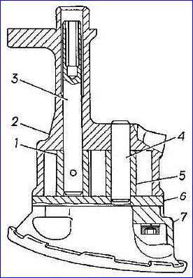
Oil pump: 1 - drive gear; 2 – body; 3 - roller; 4 - axis; 5 - driven gear; 6 - partition; 7 - inlet pipe with mesh and pressure reducing valve
The driving gear 1 is fixedly fixed on the shaft 3 using a pin, and the driven gear 5 rotates freely on the axis 4, pressed into the pump housing 2.
At the upper end of roller 3 there is a hexagonal hole into which the hexagonal shaft of the oil pump drive fits.
Centring of the pump drive shaft is achieved by fitting the cylindrical protrusion of the pump housing into the hole in the cylinder block.
The pump body is cast from aluminum alloy, the partition 6 and gears are made of cermet.
A cast aluminum alloy inlet pipe 7 with a mesh, in which a pressure relief valve is installed, is attached to the body with three screws.
Reducing valve is a plunger type, located in the inlet pipe of the oil pump. The valve plunger is made of steel and is subjected to nitrocarburization to increase the hardness and wear resistance of the outer working surface.
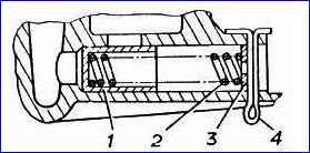
Reducing valve: 1 – plunger; 2 - spring; 3 – washer; 4 - cotter pin
The pressure reducing valve is adjusted at the factory by selecting washers 3 of a certain thickness.
Changing the valve adjustment during operation is not recommended.
The oil pump drive is carried out by a pair of helical gears from the intermediate shaft 1 of the camshaft drive.
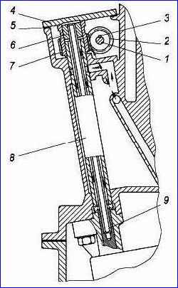
Oil pump drive: 1 - intermediate shaft; 2 - drive gear; 3 - key; 4 – cover; 5 - gasket; 6 - bushing; 7 - driven gear; 8 – roller; 9 - hexagonal shaft of the oil pump drive
The drive gear 2 is installed on the intermediate shaft using a segment key 3 and secured with a flange nut.
Driven gear 7 is pressed onto roller 8, which rotates in the bores of the cylinder block.
A steel bushing 6 with an internal hexagonal hole is pressed into the upper part of the driven gear.
A hexagonal roller 9 is inserted into the hole in the bushing, the lower end of which fits into the hexagonal hole of the oil pump roller.
On top, the oil pump drive is closed with a cover 4, secured through a gasket 5 with four bolts.
When rotating, the driven gear is pressed against the drive cover with its upper end surface.
The drive and driven helical gears are made of high-strength cast iron and nitrided to improve their wear resistance.
The hexagonal roller is made of alloy steel and carbon nitrided. Drive roller 8 is made of steel, with local hardening of the supporting surfaces by high-frequency currents.
Oil filter - full-flow, disposable oil filters of a non-separable design are installed on the engine.
Filters 2101S-1012005-NK-2 and 406.1012005-02 are equipped with a bypass valve filter element, which reduces the likelihood of unclean oil entering the lubrication system when starting a cold engine and extreme contamination of the main filter element.
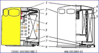
Oil filter: 1 - spring; 2 - body; 3 bypass valve filter element; 4 - bypass valve; 5 - main filter element; 6 - anti-drainage valve; 7 - cover; 8 - gasket
Oil purification filters 2101S-1012005-NK-2 and 406.1012005-02 operate as follows: oil is supplied under pressure through the holes in the cover 7 into the cavity between the outer surface of the main filter element 5 and the housing 2, passes through the filter curtain of the element 5, is cleaned and enters through the central hole of the cover 7 into the central oil line.
When the main filter element is extremely dirty or during a cold start, when the oil is very thick and has difficulty passing through the main filter element, the bypass valve 4 opens and the oil passes into the engine, being cleaned by the filter element 3 of the bypass valve.
Anti-drainage valve 6 prevents oil from leaking out of the filter when the car is parked and subsequent “oil starvation” when starting.
Filter 406.1012005-01 is designed similarly to the oil filters presented above, but does not contain filter element 3 of the bypass valve.
The oil filter must be replaced during maintenance-1 (every 10,000 km) simultaneously with an oil change.
Thermal valve - designed for automatic flow control
oil into the oil cooler depending on the oil temperature and its pressure. On the engine, the thermal valve is installed between the cylinder block and the oil filter.
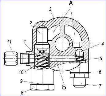
Thermal valve: 1 – plunger; 2 - thermal power sensor; 3 - thermal valve body; 4 - ball; 5 - ball valve spring; 6 - gasket; 7, 8 - plug; 9 - gasket; 10 - plunger spring; 11- fitting
The thermal valve consists of a body 3, cast from an aluminum alloy, two valves: a safety valve, consisting of a ball 4 and a spring 5, and a bypass valve, consisting of a plunger 1, controlled by a thermal power sensor 2, and a spring 10; screw plugs 7 and 8 with gaskets 6 and 9. The oil supply hose to the radiator is connected to fitting 11.
From the oil pump, oil is supplied under pressure into the cavity of thermal valve “A”. When the oil pressure is above 0.7-0.9 kgf/cm, the ball valve opens and the oil enters the channel of the thermal valve body "B" to plunger 1.
When the oil temperature reaches 81 ± 2°C, the piston of the thermal power element 2, washed by the flow of hot oil, begins to move the plunger 10, opening the way for the oil flow from channel “B” to the oil cooler.
The ball valve protects the rubbing parts of the engine from an excessive drop in oil pressure in the lubrication system.
Checking the thermal valve can be found in the article - How to check the thermal valve for the oil supply of the ZMZ-405 engine
")

")
")
")
")
")
")
")