The full travel of the brake pedal must be at least 150 mm
Adjustment of the position of the brake signal switch 1 (Fig. 1) is carried out by setting a gap (8 ± 1) mm between the end of the threaded part of the switch and the thrust pad 4 of the pedal using nuts 2 and 3.
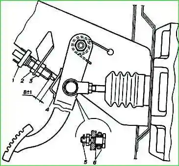
The free play of the brake pedal with a working brake system and the engine not running should be 3-5 mm (checked by pressing the pedal by hand).
The brake pedal should turn freely on its axis and return to its original position without jamming.
When moving tightly, it is recommended to lubricate the plastic bushings 6 with graphite grease.
Removing the pedal assembly
Remove the steering column lining.
Disconnect the wires from the brake light switch.
Disconnect the rods of the vacuum booster and the master cylinder of the clutch hydraulic drive from the pedals.
We tie the vacuum booster to the windshield wiper bracket and use a 13mm head to unscrew the four nuts securing the booster.
Pull it into the engine compartment so that the mounting pins come out of the holes in the engine compartment partition.
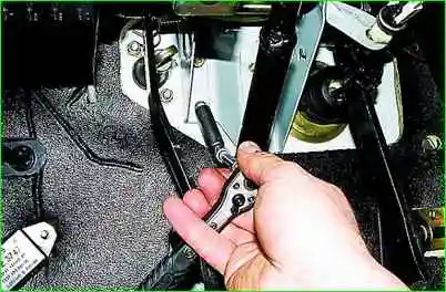
Using a 12mm socket, unscrew the two bolts securing the pedal assembly to the partition of the engine compartment.
Disconnect the wires from the battery switch.
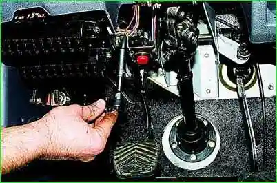
Using a 10mm socket, unscrew the two nuts securing the hazard warning switch bracket.
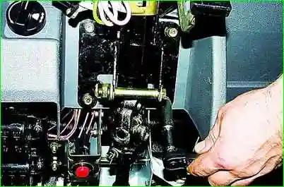
Using a 12mm socket, unscrew the four steering column mounting bolts and carefully lower the steering column onto the seat (so as not to damage the switch wires).
Remove the instrument cluster without disconnecting the wires from it (see Removing the instrument cluster)
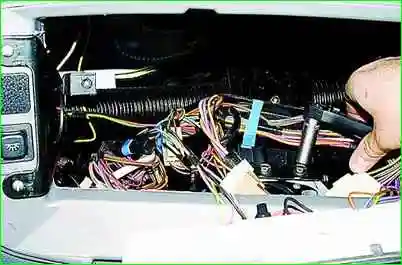
And through the resulting opening, use a 12mm head to unscrew the two bolts of the upper fastening of the pedal assembly.
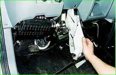
Remove the pedal assembly (the steering column has been removed for clarity).
Install the pedal assembly in the reverse order, lubricating the pedal axles with grease.


