The nozzle of the YaMZ-238 diesel engine is of a closed type, with a multi-hole atomizer and hydraulic control of the needle lift
Injectors of several models are installed on YaMZ-238 engines (see the article - Main parameters and characteristics of YaMZ-238 engines), which have design and adjustment differences.
Nozzles models 267-02 and 204-50.01
All parts of the injectors are assembled in housing 7 (Fig. 1).
The spacer 3 and the atomizer (mod. 335.1112110-50 and 204.1112110-50.01, respectively) are attached to the lower end of the nozzle body with a nut 5.
The mutual arrangement of the nozzle body, spacer and atomizer is determined by pins pressed into the spacer.
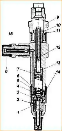
Nozzle: 1 - atomizer body; 2 - spray needle; 3 - spacer; 4 - rod; 5 - atomizer nut; 6 - spring; 7 - body; 8 - fitting with a filter; 9 - cap; 10 - nut; 11 - washer; 12 - adjusting screw; 13 - spring plate; 14 - pin; 15 - slotted filter
Inside the body 1 of the atomizer there is a locking needle 2.
The body and needle make up a precision pair.
The atomizer has five spray holes.
The tightening force of spring 6 (injection start pressure) is regulated by screw 12 screwed into the nozzle body. The screw is fixed with a nut 10.
For injector model 204-50.01, the tightening force of spring 6 is regulated by adjusting washers installed in the injector body.
Fuel is supplied to the nozzle through fitting 8 screwed into the nozzle body.
Slotted filter rod 15 is pressed into the fitting.
Fuel that has leaked through the gap between the needle and the atomizer body is discharged from the nozzle through the spring cavity and holes in the adjusting screw and cap 9.
The nozzle is installed in the glass of the cylinder head.
A corrugated washer is placed under the butt end of the atomizer nut to seal against gas breakthrough.
NOZZLE MODEL 51-01
All parts of the nozzle are assembled in housing 7 (Fig. 2). A spacer 3 and atomizer 1 (mod. 335.1112110-60) are attached to the lower end of the nozzle body with a nut 2.
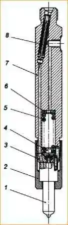
Nozzle: 1 - atomizer; 2 - atomizer nut; 3 - spacer; 4 - rod; 5 - spring; 6 - adjusting washers; 7 - body; 8 - slotted filter
The mutual arrangement of the nozzle body, spacer and atomizer is determined by pins pressed into the spacer.
There is a locking needle inside the nozzle body 1.
The body and needle make up a precision pair.
The atomizer has six spray holes.
The tightening force of spring 5 (injection start pressure) is regulated by adjusting washers 6 installed in the nozzle body.
Fuel is supplied to the injector through the fitting of the injector body, in which slotted filter 8 is installed
Fuel that has leaked through the gap between the needle and the atomizer body is discharged from the nozzle through the spring cavity and the hole in the nozzle body.
Fuel that has leaked through the gap between the needle and the atomizer body is discharged from the nozzle through the spring cavity and the hole in the nozzle body.
NOZZLE MODEL 261-11
All parts of the nozzle (Fig. 3) are assembled in body 2.
Atomizer body 4 is attached to the lower end of the nozzle body with a nut 3, inside of which there is a locking needle 5.
The needle and the atomizer body are a precision pair that can only be replaced as a complete set.
The atomizer has four spray holes and is fixed relative to the body with two pins 6.
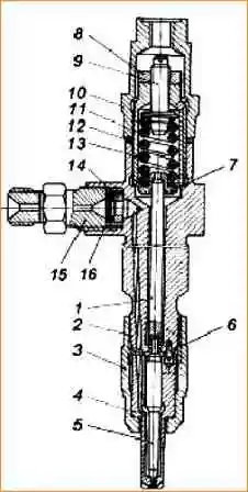
Nozzle: 1 - rod; 2 - body; 3 - atomizer nut; 4 - atomizer body; 5 - spray needle; 6 - pin; 7 - spring plate; 8 - locknut; 9 - adjusting screw; 10 - cap; 11 - spring nut; 12 - washer; 13 - spring; 14 - bushing; 15 - fitting; 16 - filter
Bar 1 with its lower end rests against the shank of the spray needle.
A plate 7 is pressed on top of the bar, against which the nozzle spring 13 rests.
Spring preload force (injection start pressure) is adjusted by screw 9 screwed into spring nut 11.
The screw is fixed with locknut 8.
A cap 10 with a sealing washer 12 is screwed onto the spring nut.
Fuel is supplied to the injector through fitting 15, in which sleeve 14 is installed, pressing the strainer 16.
Fuel leaking through the gap between the needle and the atomizer body is discharged from the nozzle through the fuel drain line.
The nozzle is installed in the brass cup of the cylinder head.
A corrugated copper washer is placed under the butt end of the atomizer nut to seal against gas breakthrough.
")

")
")
")
")
")
")
")