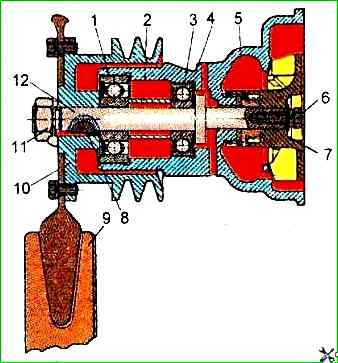
ZIL-5301 engine coolant pump
The design of the liquid pump is shown in the figure.
The liquid pump body as an assembly must be tested with water under a pressure of 0.2±0.01 MPa for 2 min. In this case, no leaks or drops are allowed.
When checking for paint, the contact area of the end surface of the support sleeve of the liquid pump housing must be at least 85% with a continuous annular imprint width of at least 2 mm.
The impeller must be statically balanced.
Residual imbalance — no more than 60 g/mm.
The mass should be adjusted by drilling holes with a diameter of 8 mm in the flat end face at a radius of no more than 37 mm.
Drill protrusion is not allowed.
The liquid pump pulley must be statically balanced.
Residual imbalance — no more than 80 g/mm.
The mass should be adjusted by drilling holes with a diameter of 8 mm in the end face at a diameter of 100 mm to a depth of no more than 8 mm.
The thickness of the bridges between the holes must be at least 5 mm.
The end of the sealing washer during assembly of the liquid pump must be covered with a thin layer colloidal graphite grease OST 6.08.430-74.
The bearing cavity should be filled with Litol-24 grease weighing 35-40 g.
The nut should be tightened to a torque of 100-120 Nm.
The impeller protruding beyond the end of the liquid pump housing is allowed to be no more than 0.4 mm, and recessing - no more than 1 mm.
The runout of the conical surfaces of the liquid pump pulley groove is allowed to be no more than 0.3 mm when the indicator is installed perpendicular to the generatrix of the conical surface.
The end runout of the liquid pump pulley flange is allowed to be no more than 0.35 mm at the extreme points.
The radial runout of the outer diameter of the liquid pump pulley hub is allowed to be no more than 0.15 mm.
The assembled liquid pump must be tested for performance on the OR-18003-07 stand.
At a pump shaft speed of 2600±20 min -1 and a back pressure of 0.03 MPa, the pump capacity must be at least 2.25 cm 3/s.
Fan
The riveted heads of the fan rivets must be at least 3 mm high and at least 7 mm in diameter.
A gap of 5 mm between the crosspiece shank and the blade around the rivet rod is not allowed.
At a distance of 5÷10 mm around the rivet rod, the gap must be no more than 0.1 mm, and at a distance of 5 mm from the inner edge of the blade - no more than 0.2 mm.
The identical side edges of the fan blades must lie in the same plane with an acceptable deviation of 3 mm.
The runout of the side edges of the fan blades is allowed to be no more than 3 mm at the extreme points.
For one fan, the difference in width blades in the plane of the crosspieces should not exceed 4 mm.
The fan assembly must be statically balanced. The residual imbalance is no more than 250 g-mm.
The mass must be adjusted by welding round or rectangular steel plates no more than 1.5 mm thick to the convex surface of the blade in an amount of no more than two per blade and no more than two blades.
The fan must be painted in a bright color that differs from the color of the diesel engine.
Since 1999, fans with an uneven X-shaped arrangement of blades have been installed on diesel engines, which are completely interchangeable with previously installed fans.