Removing the ignition coil
To check the serviceability of the ignition coil, the following checks must be performed.
The ohmic resistance of the primary winding at 20° C should be 3.07-3.5 Ohms, and the secondary winding 5400-9200 Ohms.
The ignition coil must withstand an alternating current voltage of 1500 V and 50 Hz, applied for 1 minute between one end of the primary winding and the housing, without causing discharges.
Insulation resistance to ground must be greater than or equal to 50 MOhm.
We carry out the work with the ignition off.
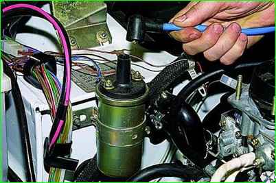
Removing the high-voltage wire
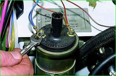
Use an 8 wrench to unscrew the two nuts securing the wires to the ignition coil
Remove the wires from the coil terminals (blue wires with a black stripe are attached to terminal “B”).
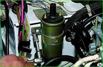
Using a 10mm socket, loosen the nuts securing the coil bracket to the body front panel
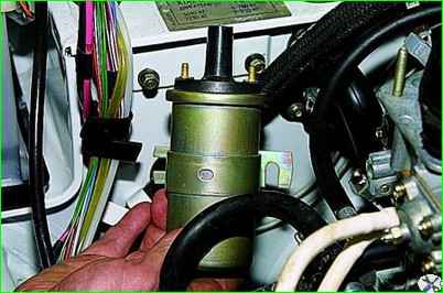
Slide the bracket along the grooves from the studs and remove the ignition coil
Install the coil in reverse order.
Removing the switch
The switch converts the control pulses of the contactless sensor into a pulse current supplied to the primary winding of the ignition coil.
The serviceability of the switch cannot be checked without special equipment.
To check, it is best to check the operation of the engine and ignition system using a known-good switch.
To avoid damaging the switch, do not disconnect its connector when the ignition is on and do not remove the battery terminals while the engine is running.
Systematically check that the commutator mass is securely fastened to the body.
We carry out the work with the ignition off.
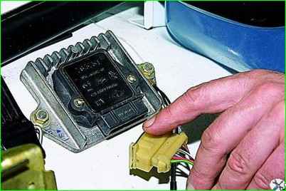
Pressing the spring lock of the wire connector, disconnect the connector from the switch block.
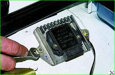
Using a 10mm wrench, unscrew the two nuts securing the switch to the right mudguard.
One of the nuts secures the ground wire
Remove the switch from the studs.
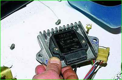
Install the switch in reverse order.


