Removing the oil pan and engine oil pump on a car
Usually the oil pump is removed for replacement or repair.
Replacement or repair of the oil pump may be caused by the following reasons:
- - insufficient oil pressure at idle with a warm engine (wear of the oil pump gears or foreign objects getting under the oil pressure relief valve).
- - a sharp drop in oil pressure after hitting an obstacle, causing deformation of the pan (in this case, the oil receiver may be broken or cracked);
- - high oil pressure on a warm engine due to jamming of the pressure relief valve.
We carry out the work on an inspection ditch or a lift.
We remove the oil separator of the engine crankcase ventilation system (see the article - "Removing the oil separator of the crankcase ventilation system").
We disconnect the pan crankcase from the cylinder block (see - "Replacing the engine oil pan gasket on a car").
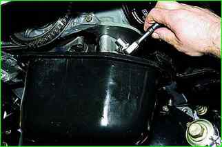
In the gap between the mating surfaces of the cylinder block and the oil pan, insert a "ratchet" with a "13" head.
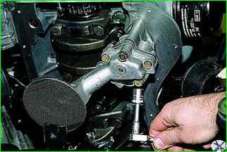
Unscrew the two bolts securing the oil pump to the cylinder block (the oil pan has been removed for clarity)
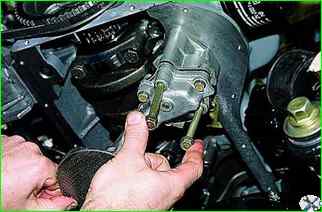
Remove the bolts securing the oil pump.
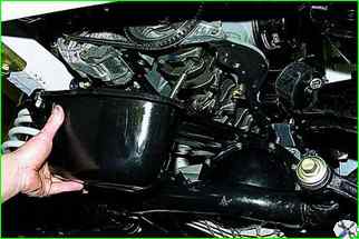
After releasing the oil pump into the oil pan, remove the pan with the pump.
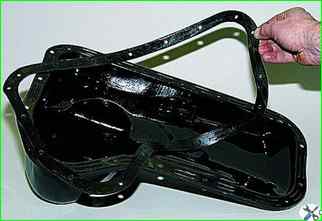
Removing the oil pan gasket
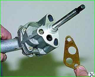
Removing the oil pump sealing gasket.
(When installing the pump, be sure to change the gasket)
Disassembling and inspecting the oil pump
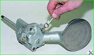
Using a 10 mm open-end wrench, loosen the three bolts securing the oil pump inlet pipe.
(One of the bolts is shorter than the others, reinstall it when reassembling)
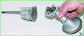
Remove inlet pipe with pressure reducing valve.
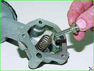
Removing the pressure reducing valve
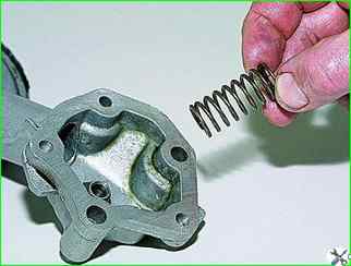
Removing the valve spring
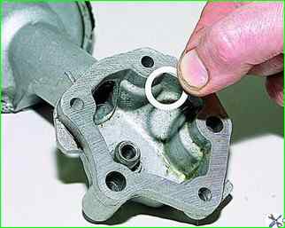
Removing the thrust washer.
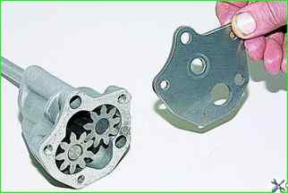
Remove the pump cover.
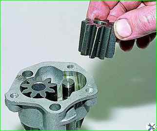
Remove the driven gear from the pump body
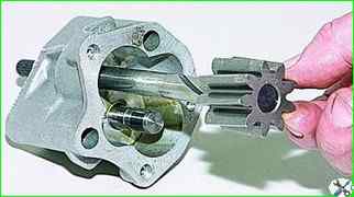
Remove the drive gear with the drive shaft
Wash the pump parts with gasoline or kerosene and blow with compressed air.
If there are cracks and severe wear of the housing, cover and gears, replace the pump.
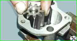
Determine (by calculating based on the results of measuring the diameters) the gap between the driven gear and its axis.
It should be 0.017–0.057 mm (the maximum permissible is 0.1 mm).
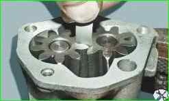
Use a feeler gauge to measure the gap between the gear teeth: it should be 0.15 mm (the maximum permissible value is 0.25 mm).
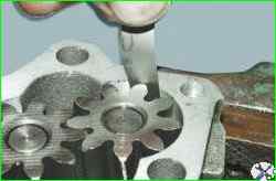
Use a feeler gauge to measure the gap between the outer diameters of the gears and the housing: should be 0.15 mm (maximum permissible - 0.25 mm).
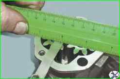
Use a flat feeler gauge, placing a ruler on the plane, to measure the gap between the ends of the gears and the plane of the housing: should be 0.161–0.166 mm (maximum permissible - 0.2 mm)
When turning the drive shaft by hand, the gears should rotate smoothly and without jamming.
After measuring the diameters of the roller and the hole in the pump housing, determine the gap between the bearing surfaces of the roller and the housing.
The gap should be 0.016–0.055 mm (maximum permissible – 0.1 mm).
Inspect the pressure reducing valve.
The surfaces mating with the pump cover should not have any damage (nicks, burrs) that cause a decrease in pressure in the system, as well as dirt or deposits that can lead to valve jamming.
Inspect the pressure reducing valve spring. It should not have any mechanical damage.
If possible, check the elasticity of the spring: the spring height should be 20 mm at a vertical load of 60.4–65.2 Nm (6.15–6.65 kgf).
The height of the spring in a free state is 38 mm.
Inspect the cover.
The surfaces mating with the pressure reducing valve, body and inlet pipe should not have any damage (nicks, burrs), as well as dirt or deposits that can lead to a decrease in pressure in the system and jamming of the valve.
If there are signs of impact on the engine crankcase, inspect the inlet pipe especially carefully.
Cracks and mechanical damage are not allowed.
Clean the inlet pipe mesh from dirt and wash it with white spirit. branch pipe.
If the mesh cannot be cleaned or is damaged, replace it or the oil receiver.
Replace worn or damaged parts.
Observing maximum cleanliness during assembly, install the removed parts and the pump in the reverse order of removal.
Do not forget to fill the engine with oil.
Tightening torques of parts when repairing the oil pump
Bolt for fastening the sprocket of the oil pump drive shaft - 41.2-51.0 N m (4.2-5.2 kgf cm);
Nut of the valve adjusting bolt - 43.3-53.5 N m (4.42-5.46 kgf cm);
Bushing of the valve adjusting bolt - 83.3-102.9 N m (8.5-10.5 kgcm);
Oil pump mounting bolt - 21.66-26.75 Nm (2.21-2.73 kgcm);
Oil pan mounting bolt - 5.10-8.20 Nm (0.50-0.85 kgcm)


