The engine cooling system is a closed-type liquid with forced circulation
The cooling system includes an engine cooling jacket, a radiator with two electric fans, an expansion tank, a thermostat, a coolant pump and a heater radiator.

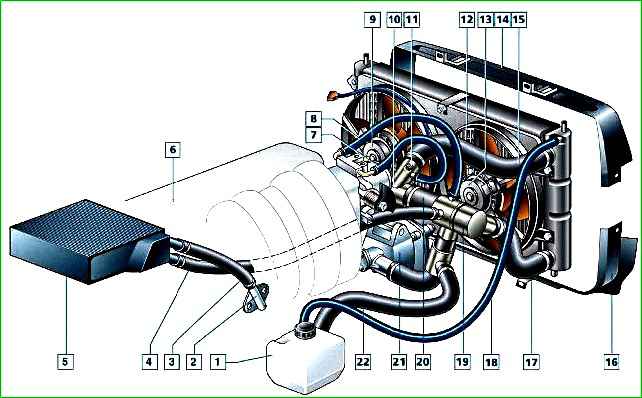
Cooling system (car without air conditioning): 1 - expansion tank; 2 - cylinder head pipe; 3 - heater radiator inlet hose; 4 - heater radiator outlet hose; 5 - heater radiator; 6 - instrument cluster coolant temperature gauge sensor (screwed into the threaded hole in the cylinder head - not visible in the figure); 7 - throttle body heater unit inlet hose; 8 - throttle body heater unit outlet hose; 9 - left electric fan; 10 - cooling jacket outlet pipe; 11 - control system coolant temperature sensor; 12 - radiator; 13 - right electric fan; 14 - radiator upper guide shroud; 15 - radiator inlet hose; 16 - radiator lower guide shroud; 17 - radiator outlet hose; 18 - air-steam hose; 19 - thermostat; 20 - bypass hose; 21 - coolant pump; 22 - filling hose
The system is filled with liquid through the neck of the expansion tank.
The tightness of the system is ensured by the inlet and outlet valves in the cap of the expansion tank.
The outlet valve maintains increased (compared to atmospheric) pressure in the system on a hot engine.
Due to this, the boiling point of the liquid increases, and steam losses decrease.
The inlet valve opens when the pressure in the system decreases relative to atmospheric (on a cooling engine).
The thermal mode of engine operation is maintained by a thermostat and electric radiator fans.

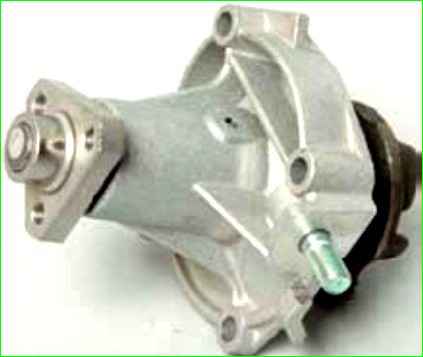
The coolant pump is a vane, centrifugal type, driven by a poly-V belt from the auxiliary drive pulley. The pump body is made of aluminum.
The pump shaft rotates in a double-row bearing with a lifetime supply of grease.
The pulley hub is pressed onto the front end of the shaft, and a plastic impeller is pressed onto the rear end.
For the correct position of the pump pulley grooves, the distance from the mating plane of the pump cover to the outer end of the hub should be 84.4±0.1 mm.
Axial and radial play in the pump bearing is not allowed.
If the bearing or self-tightening seal of the pump fails, the pump cover should be replaced together with the shaft and impeller.
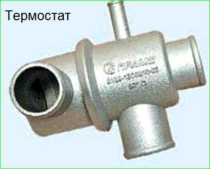
The redistribution of liquid flows is controlled by a thermostat with a solid temperature-sensitive element.

The thermostat is located above the coolant pump, on the right side of the engine.
When the engine is cold, the main thermostat valve closes the pipe leading to the radiator, and the liquid, bypassing the radiator, circulates only in a small circle - through the bypass pipe of the thermostat, the liquid from the outlet pipe of the cooling jacket enters the pump.
At a temperature of 78–82° C, the valve begins to move, opening the main pipe of the thermostat; at the same time, some of the liquid begins to circulate in a large circle, through the radiator.
At a temperature of about 90° C, the main valve opens completely, and the bypass valve closes, and most of the liquid circulates through the engine radiator.
Regardless of the state of the thermostat (the position of its valves), the liquid always circulates through the heater radiator and the throttle assembly heating unit.
The radiator consists of two vertical plastic tanks (the right one with a partition) and two horizontal rows of round aluminum tubes with pressed-on cooling plates.
To improve cooling efficiency, the plates are stamped with a notch.
The tubes are connected to the tanks through a rubber gasket. The liquid enters the radiator through the upper branch pipe and is discharged through the lower one.
At the bottom of the left tank there is a plug for draining the coolant.
On a car without air conditioning, there are upper and lower guide casings in front of the radiator of the cooling system, and on a car with air conditioning, there is an air conditioning condenser.

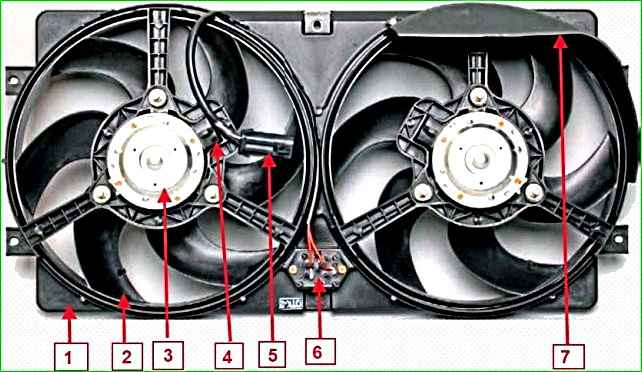
The electric fans are located behind the radiator in the casing.
As the coolant temperature increases, the controller commands the right electric fan to turn on at a low speed through an additional resistor, and then both electric fans to turn on at a high speed.
To monitor the coolant temperature, a sensor is screwed into the left rear part of the cylinder head, which is connected to the temperature gauge in the instrument cluster.
A coolant temperature sensor is installed in the outlet pipe of the cooling jacket, providing information to the controller


