The pendulum lever is removed for repair or replacement if damaged
It is more convenient to perform the work on a lift. It can also be done on a car installed on supports.
You will need: 17 and 22 mm wrenches, a puller for pressing out the ball joint pin, and pliers.
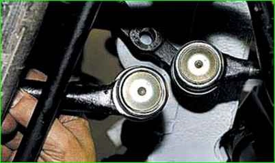
Disconnect the ball joint pins of the right side and middle steering rods from the pendulum arm (see "Replacing the steering rods Niva Chevrolet").
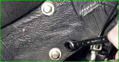
Unscrew the two bolts securing the pendulum arm bracket to the side member, holding the nuts of the bolts
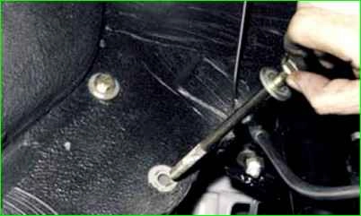
Remove the nuts, take out the bolts securing the arm bracket and remove lever from the car
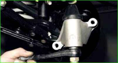
Install the pendulum lever in the reverse order of removal
Disassembly, defect detection and assembly of the pendulum lever
The pendulum lever is disassembled to replace damaged or worn parts.
You will need: a key "for 19", a special puller.
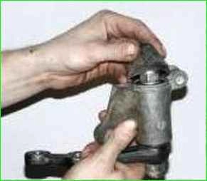
Remove the protective cap of the pendulum lever axle.
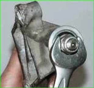
Unscrew the upper nut of the lever axle.
Please note that under A flat washer is installed with a nut. Don't forget to install it during assembly.
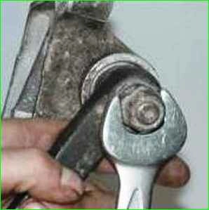
Unscrew the nut securing the lever to the axle.
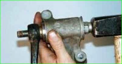
Knock out the lever axle together with the lower bearing with light hammer blows.
To avoid damaging the pendulum arm axle thread, screw the nut flush with the axle end.
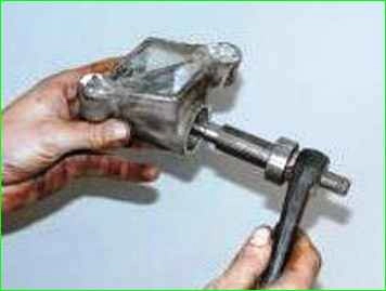
Remove the axle from the bracket.
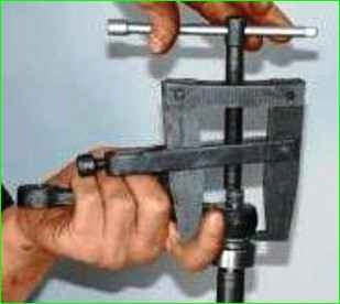
If necessary, use a puller to press the pendulum arm off the axle.
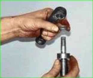
Remove the pendulum arm, spacer ring and lower bearing
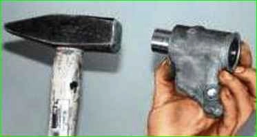
Using a suitable punch, knock the upper bearing out of the bracket
Check the condition of the pendulum lever and its axle.
The lever should not have any bends, and the lever axle should not show any signs of wear.
The axle bearings should not have any play or local wear of the raceways.
The pendulum lever bracket should not have any cracks, deformations or etc.
Assemble the pendulum arm in the reverse order of disassembly.
When pressing the bearing into the bracket, apply force only to its outer race, and when pressing onto the axle, to the inner race.
Otherwise, the bearings will be damaged.


