The VAZ-2123 engine is equipped with a microprocessor control system (MSCS), i.e. a distributed fuel injection system with feedback, which combines the inextricably linked power supply and ignition subsystems
Both subsystems are controlled as a complex by an electronic control unit (ECU), which receives information about the engine condition from sensors that monitor various operating parameters of the system.
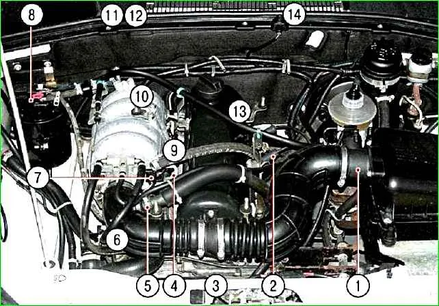
The location of the sensors is shown in Fig. 1.
The electrical diagram of the engine management system is given in the article - Wiring diagram of the Niva Chevrolet ECU
It is called distributed injection because fuel is injected for each cylinder by a separate injector.
The fuel injection system allows to reduce the toxicity of exhaust gases while improving the driving performance of the car.

Fig. 1. Location of engine management system elements in the engine compartment: 1 - mass air flow sensor; 2 - ignition module; 3 - crankshaft position sensor (not visible in the photo, installed near the crankshaft pulley); 4 - injectors; 5 - idle speed control valve; 6 - coolant temperature sensor (not visible in the photo, installed in the water jacket pipe of the cylinder head); 7 - throttle position sensor; 8 - adsorber purge valve; 9 - knock sensor (not visible in the photo, located on the right side of the engine cylinder block); 10 - oxygen sensor (not visible in the photo, located on the exhaust system inlet pipe): 11 - controller (not visible in the photo, located in the passenger compartment on the bulkhead of the front shield); 12 - relay and fuse box (not visible in the photo, installed together with the controller); 13 - vehicle speed sensor (not visible in the photo, installed on the transfer case); 14 - diagnostic connector (not visible in the photo, installed in the passenger compartment next to the ignition switch)
The VAZ-2123-40 MSUD with the Bosch MP7.OH controller (2123–1411020–10) installed on the vehicle ensures compliance with Euro II toxicity standards.
This system uses a synchronous fuel supply method. The injectors are switched on in pairs and alternately: first the injectors of the 1st and 4th cylinders, and after 180° of crankshaft rotation - the injectors of the 2nd and 3rd cylinders, etc.
Thus, each injector is switched on once per crankshaft revolution, i.e. twice per full engine working cycle.
To achieve Euro IV toxicity standards, a phased injection method can be used on some vehicles.
In this case, a phase sensor is additionally installed on the engine, which determines the moment of the end of the compression stroke in the 1st cylinder, and fuel is supplied by injectors to the cylinders in a sequence corresponding to the order of ignition in the cylinders (1–3–4–2).
Vehicles that meet Euro IV toxicity standards are not currently supplied to the domestic market, so the phased injection system is not considered in this publication.
This article describes the controller and sensors of the engine management system, as well as the ignition module.
Elements of the fuel and air supply subsystem, as well as the fuel vapor recovery system are described in the article "Features of the Niva Chevrolet fuel system".
The ignition system does not use a traditional distributor and coil ignition.
It uses an ignition module consisting of two ignition coils and high-energy control electronics.
The ignition system has no moving parts and therefore requires no maintenance.
It also has no adjustments (including ignition timing), since the ignition is controlled by a controller.
The ignition system uses a spark distribution method called the "idle spark" method.
The engine cylinders are paired 1-4 and 2-3, and spark formation occurs simultaneously in two cylinders: in the cylinder in which the compression stroke ends (working spark), and in the cylinder in which the exhaust stroke occurs (idle spark).
Due to the constant direction of current in the windings of the ignition coils, the spark current for one spark plug always flows from the central electrode to the side, and for the second - from the side to the central.
Controls ignition in the system controller.
The crankshaft position sensor sends a reference signal to the controller, based on which the controller calculates the sequence of operation of the coils in the ignition module.
For precise ignition control, the controller uses the following information:
- – crankshaft speed;
- – engine load (mass air flow);
- – coolant temperature;
- – crankshaft position;
- – presence of detonation.


