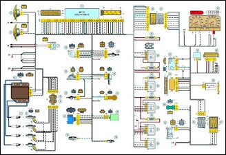
Electrical connection diagram of the Niva Chevrolet engine management system
The wires in this diagram have a letter designation of color and a designation of the number of the circuit element to which this wire is connected
The number of the connector contact is indicated after a slash.
ECM Wiring Diagram: 1 – Controller; 2 – Right Engine Cooling Fan; 3 – Left Engine Cooling Fan; 4 – Ignition Module; 5 – Spark Plugs; 6 – Injectors; 7 – Resistor; 8 – Ignition Harness Connector to Injector Harness; 9 – Injector Harness Connector to Ignition Harness; 10 – Oil Pressure Warning Lamp Sensor; 11 – Mass Air Flow Sensor; 12 – Coolant Temperature Sensor; 13 – Throttle Position Sensor; 14 – Idle Speed Control Valve; 15 – Oxygen Sensor; 16 – Crankshaft Position Sensor; 17 – Knock Sensor; 18 – Evaporative Canister Purge Solenoid Valve; 19 – Coolant Temperature Gauge Sensor; 20 – Additional Relay; 21 – Right electric fan relay; 22 – Right electric fan power supply circuit fuse; 23 – Left electric fan relay; 24 – Left electric fan power supply circuit fuse; 25 – Electric fuel pump relay; 26 – Electric fuel pump power supply circuit fuse; 27 – Ignition relay fuse; 28 – Ignition relay; 29 – Controller power supply circuit fuse; 30 – Ignition system harness connector to instrument panel harness; 31 – Instrument panel harness connector to ignition system harness; 32 – Ignition switch; 33 – Vehicle anti-theft system; 34 – Vehicle speed sensor; 35 – Electric fuel pump; 36 – Instrument cluster; 37 – Mounting block; 38 – Diagnostic connector; 39 – Indicator lamp unit; 40 – Instrument panel harness connector to rear harness; 41 – rear harness connector to instrument cluster harness; A – to negative battery terminal; B – to positive battery terminal; C1, C2 – ignition system harness grounding points; C3 – instrument cluster harness grounding point; C4 – rear harness grounding point.
The symbol “S28” or “SB” means that the wire is connected to circuit element number 28 or designated by letter B via a connection point not shown in the diagram


