The ignition system uses a 4-pin ignition coil, which is a block of two 2-pin ignition coils
The ignition system has no moving parts, and therefore does not require maintenance and adjustments, with the exception of spark plugs.
The current in the primary windings of the ignition coils is controlled by the controller, using information about the engine operating mode received from the sensors of the engine management system.
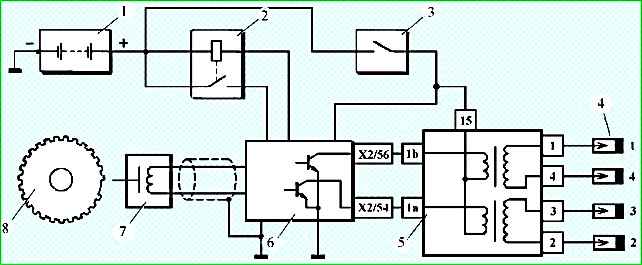
To switch the primary windings of the ignition coils, the controller uses two powerful transistor valves (Fig. 1).
The ignition system uses a spark distribution method called the "idle spark" method.
The engine cylinders are combined into pairs 1-4 and 2-3, and spark formation occurs simultaneously in two cylinders: in the cylinder in which the compression stroke ends (working spark), and in the cylinder in which the exhaust stroke occurs (idle spark).
Due to the constant direction of current in the primary and secondary winding, the spark current of one spark plug always flows from the central electrode to the side electrode, and the second one - from the side electrode to the central one.
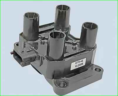

Four-pin ignition coil (Fig. 2) has the following circuits (see Fig. 1):
Primary winding power supply circuit (Fig. 1)
The voltage from the vehicle's electrical system comes from the ignition switch to contact "15" of the ignition coil.
Primary winding circuit of the ignition coil of cylinders 1 and 4, contact "1b"
The controller switches the primary winding circuit of the ignition coil, which supplies high voltage to the spark plugs of cylinders 1, 4, to ground.
Primary winding circuit of the ignition coil of cylinders 2 and 3, contact "1a"
The controller switches the primary winding circuit of the ignition coil, which supplies high voltage to the spark plugs of cylinders 2, 3, to ground.
The ignition coil is non-separable; if it fails, it replace.
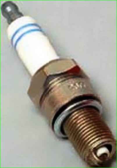
Spark plugs — A17 DVRM or their analogues with a noise suppression resistor (resistance 4–10 kOhm) and a copper core.
The gap between the electrodes is 1.0–1.1 mm.
Engine detonation suppression
To prevent engine failure as a result of prolonged detonation, the ECM adjusts the ignition timing.
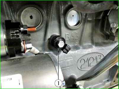
The system has a knock sensor 1 (Fig. 5) to detect knock
The controller analyzes the signal from this sensor and, upon detecting knock, characterized by an increase in the amplitude of engine vibrations in a certain frequency range, adjusts the ignition timing according to a special algorithm.
The ignition timing adjustment to suppress knock is performed individually for each cylinder, i.e. determines in which cylinder detonation occurs, and the ignition timing is reduced only for that cylinder.
In the event of a knock sensor malfunction, the corresponding fault code is entered into the controller memory and the
fault indicator is turned on. In addition, in certain engine operating modes, the controller sets a reduced ignition timing, eliminating the occurrence of detonation.
")

")
")
")
")
")
")
")