The gas distribution mechanism controls the timely intake of air charge into the cylinders and the removal of exhaust gases from them; consists of valves with springs, a camshaft with gears and parts that transmit movement from the shaft to the valves
The crankshaft rotates camshaft 1 through gears.
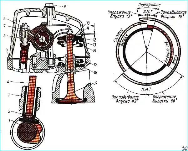
The protrusion of the cam shaft lifts the pusher 2 together with the rod 4, the rocker arm 6 rotates on the axis and lowers the valve 17, compressing its springs 13 and 14.
As the shaft rotates further, the cam protrusion comes out from under the pusher, the pressure on the valve stops and, under the action of compressed springs, it rises in the sleeve, tightly closing the hole in the cylinder head.
For one working cycle of a four-stroke engine, that is, for two revolutions of the crankshaft, the valves must open and close the holes in the cylinder head only once. In this case, the camshaft makes one revolution.
Engine power depends on filling the cylinders with a fresh charge of air and the degree of their purification from exhaust gases.
In order for more air to flow into the cylinders, the intake valve opens ahead of time, i.e. before the piston arrives at m.t.
The filling of the cylinder begins from the suction action of the piston, and under the influence of inertial pressure in the intake pipeline, which is created as a result of frequently repeated strokes.
The intake valve closes with oblivion, i.e. after the piston arrives in the i.m. i.e., because air continues to flow into the cylinder by inertia and the pressure in it is even lower than atmospheric.
The exhaust valve also opens ahead of time, i.e. before the end of the power stroke, and some of the gases under low pressure are ejected from the cylinder.
This reduces the back pressure of the gases remaining in it, reducing the power required to push them out.
The exhaust valve closes with a delay, i.e. after c. m.t., providing better cleaning of the combustion chamber from exhaust gases.
At some point, both valves are slightly open at the same time.
The so-called valve overlap occurs, in which the gases leaving the cylinder help suck air into the cylinder, increasing its filling.
The duration of the open position of the valves, expressed in degrees of rotation of the crankshaft, is called valve timing.
In Fig. Figure 1 shows a diagram of such phases, from which it is clear at what position of the connecting rod journal relative to the dead points the valves open and close.
The phase diagram is provided by the shape and relative position of the camshaft cams, as well as a certain gap between the valve stems and the rocker tips.
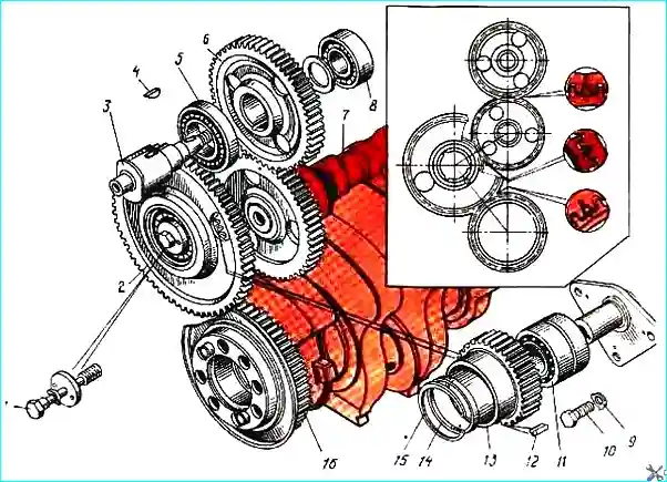
The camshaft is driven from the crankshaft through the drive gears of the units. The installation of the camshaft drive gears and assemblies is shown in Fig. 2.
At the end of each gear there are “O” marks or marks, the coincidence of which must be ensured when assembling the engine to ensure correct valve timing.
The camshaft is made of steel, the working surface of its cams and bearing journals is cemented and hardened by high-frequency currents.
The cam profile is not the same for the intake and exhaust valves.
The camshaft is installed in the camber of the cylinder block on five plain bearings, which are steel bushings filled with an antifriction alloy.
A spur gear is mounted on the rear end of the camshaft.
The camshaft fixes the axial movement with a rear support bearing installed in the housing.
The gear hub rests on the ends of the housing on one side, and the thrust collar of the rear shaft support journal on the other.
The bearing housing is attached to the cylinder block wall with three bolts.
Valve pushers are steel, hollow, disc type with a cylindrical guide part.
To improve the performance of the cam-pusher pair, the end of the pusher plate is overlaid with bleached cast iron.
The end of the pusher in contact with the rod ends in a spherical socket for resting the lower end of the rod.
Valve tappets are installed in guides bolted to the cylinder block.
Push rods are hollow with pressed-in tips.
The lower tip has a convex spherical surface, the upper one is made in the form of a spherical cup for the stop of the rocker arm adjustment screw.
Valve rocker arms are forged steel double-arm levers with pressed-in bronze bushings.
The tip of the long arm rocker arm is hardened to high hardness. To reduce the stroke of the pusher and rod, as well as to reduce inertia forces, the rocker arms are made of unequal arms.
An adjusting screw with a lock nut is screwed into the short arm of the rocker to set the required clearance between the rocker and the end of the valve stem.
The rocker arms of the intake and exhaust valves are mounted in cantilevers on axles made integral with the rocker arms.
The posts are fixed with pins and fastened to the head with studs. Lubricant is introduced into each rocker through a hole in the rack.
The rocker arm bearings are bronze bushings.
The valves are made of heat-resistant steel. Each cylinder has one intake and one exhaust valve.
The valve stems are mixed in cermet guide bushings pressed into the cylinder head.
To improve running-in, valve stems are coated with graphite before assembly.
The rods are lubricated with oil, which flows out of the rocker arm interface with the axles and is sprayed by the valve springs.
To better fill the cylinders with fresh air, the diameter of the intake valve plate is larger than the diameter of the exhaust valve plate.
Each valve has two coil springs with a uniform pitch and counter-winding, which provides a high resonant characteristic of the valve mechanism.
Different directions of the turns of the outer and inner springs, when one of them breaks, prevents its turns from getting between the turns of the other.
The lower ends of the spring rest on the cylinder head through a steel washer, and the upper ends rest on the thrust plate.
The latter rests on a conical bushing, which is connected to the valve stem by two conical nuts.
The detachable connection between the sleeve and the plate has slight friction during relative movement, which allows the springs, when compressed, to rotate the valves relative to the seats (since the spring twists somewhat when compressed).
This ensures uniform wear of the working surfaces and uniform heating of the valves during operation.
Maintenance of the gas distribution mechanism
The main work during the maintenance of the crank and gas distribution mechanisms is checking and, if necessary, adjusting the gaps between the valves and rocker arms, as well as listening to the running engine to detect knocks and replacing worn or broken parts.
The clearance in the valve mechanism must ensure a tight fit of the valve to the seat when the rod elongates due to heating and in the event of the head settling in the seat due to wear of the chamfers.
We look at adjusting valve clearances in the article - “How to adjust Kamaz valve clearances.”
During operation, the normal operation of the gas distribution mechanism may be disrupted, since hot gases destroy the seating surfaces of the valve plates and their seats, and carbon deposits are deposited on the valve heads.
This leads to a violation of the tight fit of the valve to the seat, resulting in possible gas leaks and overheating of the valve.
The rubbing surfaces of the mechanism parts gradually wear out, and the gap between the valves and rocker arms is compromised. This leads to a change in valve timing.
The most noticeable external sign of a mechanism malfunction is knocking in the area where the valves, camshafts and camshaft are located.
During engine operation, the crank mechanism parts operate reliably and do not require periodic maintenance.
As a result of violation of operating rules or careless assembly, malfunctions in the operation of the mechanism and (or) premature wear of its parts are possible.
A sign of increased wear of parts of the cylinder-piston group or the occurrence of piston rings is an increased consumption of crankcase oil due to waste, smoky exhaust and intense release of gases from the breather.
The condition of the crankshaft bearings (clearances) is characterized by the oil pressure in the main line.
If it drops, it is necessary to check the serviceability of the pressure gauge, filters, valves, oil pump and supply pipelines.
After making sure that the listed elements are in good condition, open the main and connecting rod bearings and determine the condition of the rubbing surfaces of the journals and liners.
Knocks during engine operation are heard at different crankshaft speeds using a lightoscope.
The reason for their occurrence is determined by some characteristic shades of knocking in the corresponding areas of their listening.
")

")
")
")
")
")
")
")