Center differential of a KamAZ car
The center differential is mounted in housing 3, which is mounted on the main gear housing of the intermediate axle.
It consists of the bevel differential itself, the locking mechanism and the locking control drive.
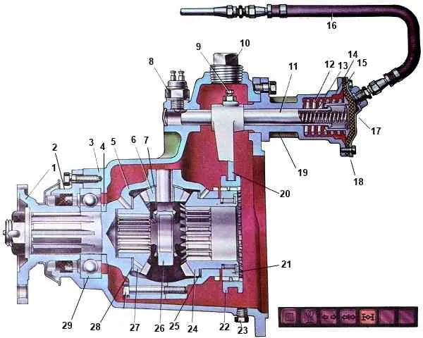
The differential housing consists of two halves (cups) connected by bolts.
The front cup has a shank that rests on a 29 ball bearing.
Flange 1 is installed on the splined part of the shank for connection to the cardan drive.
A crosspiece 26 is clamped between the halves of the body, on the spikes of which four satellites 6 with support washers 7 are installed.
The satellites are in mesh with gears 24 and 27 of the drive of the intermediate and rear axles.
Since the satellites act on the teeth of these gears with equal forces and their sizes are the same, the torques on the drive gears of the rear and intermediate axles are also the same, i.e. the differential is symmetrical.
Gear 27 of the rear axle drive is installed in the differential housing; a support washer 28 is placed under its end. The housing has a channel for supplying oil to the support washer and the gear hub.
With splines made along the inner surface of the hub, gear 27 is connected to the splined end of the rear axle drive through shaft.
Gear 24 of the intermediate bridge drive is connected by splines made on the inner surface of the hub to the elongated hub of the drive bevel gear of the main transmission of the intermediate bridge.
At the end of the gear hub 24, a gear coupling 21 is installed on the splines, along the outer part of which the center differential locking coupling 22 can move.
This coupling is connected by a fork 20 to a slider 11 connected to the locking control mechanism.
The housing 19 of the locking mechanism is mounted on the center differential housing.
A rubber membrane 15 is clamped between the body and the cover 18. The cavity behind the membrane (from the cover side) is connected by a hose 16 to the differential lock valve.
The slider 11 is connected to a cup 14, inside of which a pressure spring 13 is installed, and a return spring 12 is installed outside.
The lever for switching the center differential lock is located on the instrument panel in the vehicle cabin.
On the instrument panel there is also a warning lamp for turning on the center differential lock.
In the position shown in the figure, the center differential is unlocked.
To lock the differential, the switch valve lever located on the instrument panel is moved to the right position.
In this case, compressed air from the control valve through the piping system and hose 16 enters the cavity between the housing cover and the membrane, which bends, moves the glass 14 and the slider 11 forward, overcoming the resistance of the return spring 12.
As soon as the slider begins to move, the contacts of switch 8 close and the warning lamp on the instrument panel lights up.
Together with the slider, the fork 20 mounted on it also moves, which engages the clutch 22 with the ring gear on the differential housing.
When the clutch is in the extreme left position, gear 24 of the intermediate axle drive and the differential housing are rigidly connected, i.e., the differential is locked, and gears 24 and 27 of the axle drive are forced to rotate at the same frequency.
To unlock the center differential, the control valve lever on the instrument panel is moved to the left position.
In this case, the cavity of the differential locking mechanism will be connected to the atmosphere through the control valve and pipelines.
Under the action of the return spring, the membrane and the slider with the fork move to the right (backward), simultaneously displacing the locking clutch so that it is disconnected from the gear ring of the differential housing.
According to the general design, the main gears of the intermediate and rear drive axles of the KamAZ vehicle-4310 are similar to the corresponding main gears of the KamAZ-5320 vehicle.
The main drive of the intermediate axle differs from the main drive of the rear axle by a drive shaft with a gear, a thrust washer and a flange on the transfer case side.