Checking and replacing brushes and voltage regulator with motor ZMZ-405, ZMZ-406
On engines of the ZMZ-406 and ZMZ-405 families, generators 9422.3701 or 5122.3771 with built-in integrated voltage regulators are installed
Checking the serviceability of the voltage regulator
In order to verify that the voltage regulator is faulty, we turn off all consumers except the side light and measure the voltage at 1000-1200 min –1, which should be in the range of 13.5-14.2 V .
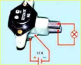
Connect a 12 V test lamp to the brushes.
Apply a voltage of 12 V “+” to the terminal, and “-” to the “ground” of the brush holder.
The indicator lamp should light up.
If the control lamp does not light, the voltage regulator must be replaced.
Replacement of generator voltage regulator 9422.3701 or 5122.3771
The voltage regulator is made in a single housing with a brush holder.
Disconnect the battery.
Disconnect the wires from the generator terminals, remove the plug from the generator plug terminal.
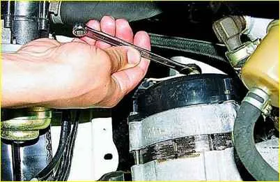
Use a 10mm wrench to unscrew the nut
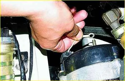
Remove the ends of the capacitor wire from the “+” terminal of the generator
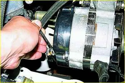
Use an “8” wrench to unscrew the capacitor mounting nut
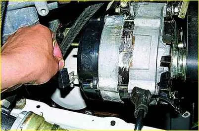
Remove the capacitor.
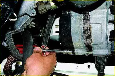
Using an “8” socket, unscrew the two nuts securing the plastic casing of the generator
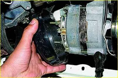
Remove the casing
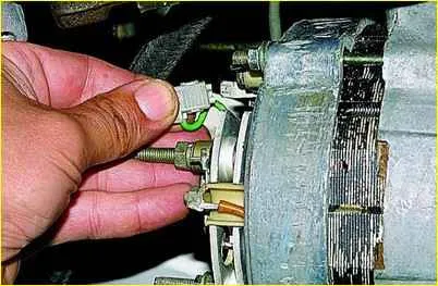
Remove the plug block from the output of the voltage regulator.
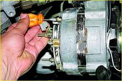
Use a short screwdriver to unscrew the two screws securing the regulator to the generator
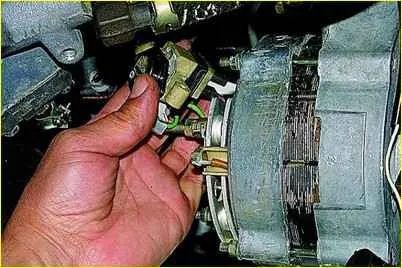
Remove the voltage regulator assembly with brush holder
Install the new regulator in reverse order.
Checking the serviceability of brushes and brush holder
Check the protrusion “a” of the brushes from the brush holder.
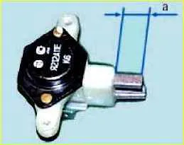
If the free brush protrusion dimension “a” is less than 4.5 mm, replace the brush holder assembly with the voltage regulator.
We replace the brush holder with worn brushes as an assembly.
Checking and replacing brushes and voltage regulator with motor type ZMZ-402
On cars with engines ZMZ-4025 and ZMZ-4026, generators 16.3701 or 191.3701 are installed, not equipped with a built-in voltage regulator.
These generators work in conjunction with an external transistor voltage regulator type 13.3702-01 or 50.3702, having electronic protection against short circuits in the generator field winding circuit.
The regulator is installed in the engine compartment and attached to the mudguard of the engine compartment with two nuts.
The regulator provides a battery charging voltage of 13.4 - 14.7 V at a generator speed of 2800 - 12,000 min -1, corresponding to an engine speed of 1400 - 6000 min - 1, load 5 - 40 A and temperature from -20 to +80 °C.
At terminals “Ш” and “-” of the regulator, the voltage drop should be no more than 1.6 V at a current of 4 A in the generator excitation winding circuit and a temperature of +20 °C.
Before checking the regulator, make sure that the generator belt tension is normal and that the regulator has good contact with ground (if necessary, adjust the belt tension and tighten the nuts securing the regulator to the body).
You should not connect additional electrical consumers to the power supply circuit of the generator excitation winding, since in this case the generator voltage increases greatly.
1. Before checking the voltage regulator, check the condition of the wires and the reliability of the connections between the generator, voltage regulator and battery.
It should be taken into account that the lack of charging current may be caused by the operation of the regulator protection circuit in the event of a short circuit in the generator excitation winding circuit.
When the short circuit is eliminated, the operation of the voltage regulator is restored.
2. The voltage regulator can be checked on the car. To do this, you need a DC voltmeter with a measurement limit of up to 20 - 30 V and a division value of 0.1 - 0.2 V.
Start the engine and, maintaining the engine speed of 1700-2000 min -1, turn on the low beam headlights. In this case, the charging current according to the ammeter should be no more than 10 A.
If the ammeter shows a charging current greater than 10 A, turn off the low beam headlights and side lights.
Measure the voltage at the “+” terminal of the battery, it should be 13.9 - 14.6 V at a regulator temperature of +20 °C.
If the voltage differs from the specified values, the voltage regulator is faulty and needs to be replaced.
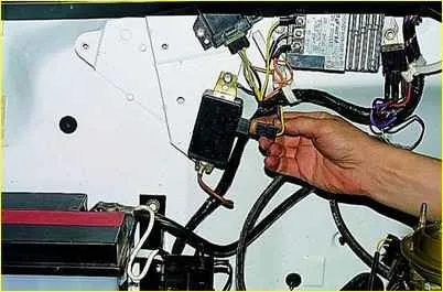
Disconnect the plug from the voltage regulator.
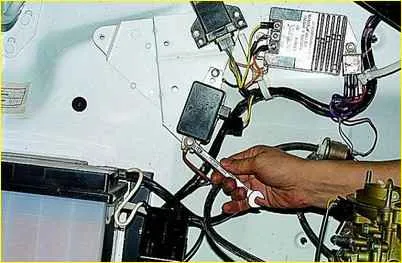
Use a 10mm wrench to unscrew the two bolts securing the regulator. Under each of the bolts there are tips of “mass” wires
Remove and replace the regulator. We install the new regulator in the reverse order.
Removing and checking generator brushes
Disconnect the battery.
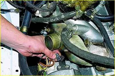
Disconnect the plug block from the brush holder.
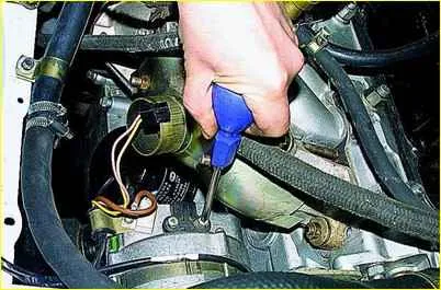
Use a slotted screwdriver to unscrew the two screws securing the brush holder
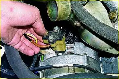
Remove the brush holder. Install the new brush holder in reverse order
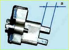
Check that the brushes move easily in the brush holder. If the brushes are stuck, remove the two mounting screws and remove the brush holder cover.
Clean the brushes and clean the holes in the brush holder. If the required result cannot be achieved, replace the brush holder assembly or brushes
Brushes with chips, cracks or other defects must also be replaced.
Check the protrusion “a” of the brushes from the brush holder in a free state.
If dimension “a” is less than 8 mm, replace the brush holder assembly or brushes.


