Mass air flow sensor - thermopneumatic type IVKSH 407282000, installed in the intake system after the air filter
The sensor detects the amount of air entering the cylinders while the engine is running.
There is a platinum filament in the sensor housing. During operation, it heats up to a temperature of 150 ° C.
The air flow passing through the sensor housing removes more heat from it, the higher the air flow rate.
The electronic unit calculates the mass flow rate of the incoming air by the amount of electric power that is spent to maintain the set temperature of the thread.
Since the temperature of the air itself affects the cooling of the thread, a thermistor is installed in the sensor housing, which changes its resistance in accordance with the temperature of the air flow entering the system.
Based on its readings, the electronic unit makes adjustments to the operation of the electrical circuit for heating the thread, thereby compensating for temperature fluctuations caused by changes in weather conditions.
The control system informs the driver about the occurrence of a malfunction in the mass air flow sensor circuit by turning on the KMSUd signaling lamp, the fault codes are stored in the memory of the electronic unit (see "diagnostics of the control system"), and the engine will be switched to standby mode.
Disconnect the wire from the "negative" terminal of the battery.

Prying off the spring clip of the block with an awl, disconnect the sensor connector.

Loosen the clamp screws with a screwdriver.

Remove the clamps.

Remove the mass air flow sensor from the air ducts.

We put short pieces of a thin polyvinyl chloride tube on the pins of the electrical connector.

Having inserted the ends of the wires bare by 7-8 mm into them, we assemble the circuit shown in the figure.
When connecting the wires to the sensor, you need to be guided by the profile of the end of the connector.
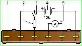
Mass air flow sensor test circuit

We connect the wires to the battery last, making sure that the circuit is assembled correctly

We take the readings of the voltmeter with the device switch turned off.
For a working sensor, the voltage at terminals "2" and "3" should be 1.3-1.4 V

Turn off the switch for a short time and take the readings of the voltmeter
A working sensor has voltage at the terminals "2" and "3" should increase to about 8 V.

Turn on the switch for a short time and take the readings of the voltmeter.
The platinum thread is heated red-hot.
A defective sensor must be replaced.
Install the mass air flow sensor in reverse order.
")

")
")
")
")
")
")
")