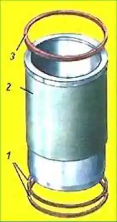
Cylinder liners are "wet" type, made of special cast iron
The liners are installed with their seat belts in the bores of the cylinder block and are pressed from above through the shoulder and the gasket by the cylinder heads
Protrusion of the liner shoulder above the surface of the cylinder block on engines:
- YaMZ-238BE2, YaMZ-238DE2 - 1.6+0.035/-0.065 mm.
- YaMZ-238BE, YaMZ-238DE - 0.1+0.065/-0.035mm.
Liners with the following design features can be installed on YaMZ-238BE, YaMZ-238DE engines:
Sleeve 236-1002021-А5
Sleeve surfaces are phosphated.
Phosphated layer improves lapping characteristics, increases wear resistance of the surface, reduces the likelihood of chafing.
The external difference between a phosphated sleeve and a non-phosphated sleeve is a much darker (from dark gray to black) color of the outer surface.
The upper end of the collar of the sleeve is made with a protruding part to the inner surface of the sleeve (under the asbestos-steel gasket of the gas joint) with a collar height of 12.1 mm.
In the lower part of the sleeve there are three grooves for anti-cavitation and sealing rubber rings.
Sleeve 236-1002021-A
The design features are similar to the previous one, but there is no phosphate coating on the surface of the sleeve.
A phosphated sleeve 7511.1002021-01 is installed on YaMZ-238BE2, YaMZ-238DE2 engines.
The upper end of the collar is made with a protruding part towards the outer surface (under the metal gasket of the gas joint) with a collar height of 9.6 mm.
A groove is made on the upper seating surface for installing a rubber sealing ring.
In the lower part of the sleeve there are three grooves for anti-cavitation and sealing rubber rings.
By the size of the inner diameter, the sleeves are divided into size groups:
Marking - Smallest inner diameter, mm
- - A - 130.00-130.02;
- - B - 130.02-130.04;
- - F - 130.04-130.06;
The size group is marked on the non-working surface of the sleeve shoulder.
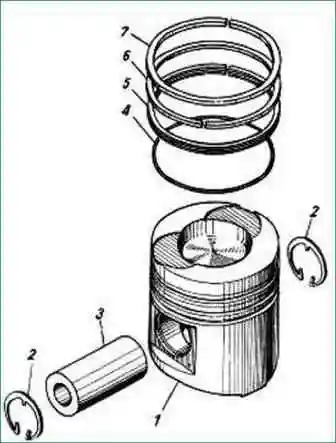
Pistons (fig. 2) are cast from a eutectic aluminum-silicon alloy.
The piston is cooled with oil from a stationary nozzle.
The piston skirt has a notch for the cooling jet. A combustion chamber is made in the bottom of the piston.
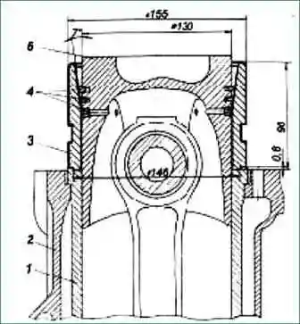
Pistons 7511.1004015-10 with 3 grooves for piston rings (two for compression and one for oil scraper) are installed on YaMZ-238BE2, YaMZ-238DE2 engines.
The groove for the upper compression ring is made in an insert made of heat-resistant cast iron (niresist type).
The combustion chamber is offset by 5 mm, the side surface is undercut, it has a displacer.
On the bottom there are grooves for gas distribution valves.
The height from the bottom to the axis of the finger is 85 mm. Piston pin diameter 52 mm.
Pistons 7511.1004015-01 with a central combustion chamber and modified valve grooves are installed on YaMZ-238DE2 engines (individual heads).
The rest is the same as on the previous piston.
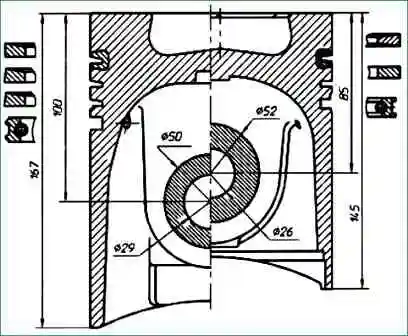
Pistons with the following design features can be installed on YaMZ-238BE, YaMZ-238DE engines:
1. Piston 238NB-1004015-B4 with 4 grooves for piston rings (three for compression and one for oil scraper).
The groove for the upper compression ring is made in an insert made of heat-resistant cast iron (ni-resist type) in order to increase wear resistance.
The combustion chamber is offset by 5 mm, the side surface is undercut, it has a displacer.
The height from the bottom to the axis of the finger is 100 mm.
Piston pin diameter 50 mm.
2. Piston 238NB-1004015 is cast from a hypereutectic aluminum-silicon alloy and is similar to the previous one, but it does not have a "ni-resist" insert for the upper compression ring.
Cameras and combustion is displaced by 5 mm, without displacer.
This piston is supplied with a sleeve for spare parts in kits 238NB-1004008 and 238NB-1004005-A3.
The pistons are divided into size groups according to the diameter of the skirt:
Marking - Piston skirt diameter, mm
238NB-1004015-B4, 238NB-1004015
- - NSA - 129.80-129.82;
- - BNB - 129.82-129.84;
- - WNB - 129.84-129.86;
7511.1004015-01, 7511.1004015-10
- - NSA - 129.85-129.87;
- - BNB - 129.87-129.89;
- - WNB - 129.89-129.91;
The size group is marked on the piston head.
Piston rings made of special cast iron, split, chrome-plated, installed in the piston grooves.
Depending on the task performed in the workflow, the rings have a different design and are installed on the piston as a set in a certain order.
The following sets of rings can be installed on pistons:
Three-ring kit 7511.1004002, where:
- − the first compression has a double-sided trapezium in cross section with a barrel-shaped chrome-plated working surface shifted down. Ring number 7511.1004030
- - the second compression ring of rectangular section, minute with chromium coating. Ring number 7511.1004032
- − box-section oil scraper ring with chrome-plated working edges and coiled spring expander. Ring number 7511.1004034
Four-ring kit for factory installation, which is included in kit 238B-1004005, where:
- − the first compression has a one-sided trapezoid in cross section.
The work surface is hard chrome plated. Ring number 236-1004030-B.
- − the second and third compression rings have a one-sided trapezium in cross section, minute. Ring number 236-1004032-А3
- − box-section oil scraper rings with chrome-plated working edges and coiled spring expander. Ring number 236-1004034
Four-ring kit 236-1004002-А4, where:
- − the first compression has a one-sided trapezoid in cross section.
The working surface is chrome-plated with porous chrome. Ring number 236-1004030-А2
- − the second and third compression rings have a one-sided trapezium in cross section, minute. Ring number 236-1004032-А3
- − box-section oil scraper rings with chrome-plated working edges and coiled spring expander. Ring number 236-1004034
When installing the piston rings, pay particular attention to their correct position. The word "Top" must face the bottom of the piston.
Piston and sleeve must be selected from the same size groups during assembly to ensure a precise fit.
It is allowed to install sets of sleeve-piston of different size groups in different engine cylinders.
Sleeve marking - Piston marking
- A - NSA;
- B - BNB;
- F - WNB
Piston pin of YaMZ-238BE, YaMZ-238DE engines - hollow, floating type with a cemented outer surface.
The pin is installed in the hole in the piston.
The axial movement of the pin is limited by retaining rings installed in special grooves in the piston bosses.
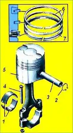
The piston pin of YaMZ-238BE2, YaMZ-238DE2 engines is nitrided, has an increased outer diameter (Fig. 5).
Assembly options sleeve - piston - piston rings
By design features:
YaMZ-238BE2, YaMZ-238DE2 (common cylinder heads)
- Sleeve - for metal gasket 7511.1002021-01
- Ring set - 3-ring set 7511.1004002
- Piston - Offset 7511.1004015-10
YaMZ-238DE2 (individual cylinder heads)
- Sleeve - for metal gasket 7511.1002021-01
- Ring set - 3-ring set 7511.1004002
- Piston - With central combustion chamber 7511.1004015-01
YAMZ-238BE, YAMZ-238DE (common cylinder heads)
Main option:
- Sleeve - phosphated 236-1002021-А5;
- Set of rings - 4-ring with dense chrome (factory equipment);
- Piston - With 4 grooves and niresist insert 238NB-1004015-B4
Allowed options (for engine repair):
- Sleeve - Non-phosphated 236-1002021-A;
- Ring set - 4-ring with porous chrome 236-1004002-А4;
- Piston - With 4 grooves and low-resist insert 238NB-1004015-B4 or without insert 238NB-1004015
In operation, when repairing running engines, it is permissible to install new piston rings in an old cylinder liner that is in good condition, while using only a set of piston rings with porous chrome 236-1004002-A4. Other options are not allowed
Replacing piston rings
To replace the piston rings, first dismantle the piston with the connecting rod with the cylinder head and sump removed.
Engines are equipped with oil-cooled pistons.
When dismantling the piston group on the indicated engines, first remove the piston cooling nozzles to avoid damage.
For easier removal of the piston, clean the carbon deposits from the upper belt of the sleeve.
Unscrew the connecting rod cover bolts, remove the cover and remove the piston assembly with the connecting rod through the cylinder.
To disconnect the connecting rod from the piston, remove the piston pin circlips, heat the piston in an oil bath to 80ºС and remove the piston pin.
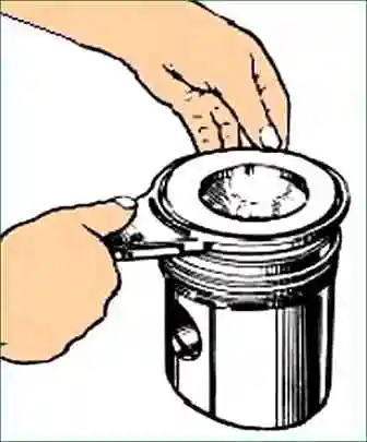
To remove the piston rings, put pliers (Fig. 6) on the ring, insert the jaws of 2 pliers into the ring lock and, squeezing the handles of 3 pliers to the stop, carefully remove the ring from the groove and remove it from the piston (Fig. 7).
Install the piston rings in reverse order.
Carefully clean the piston from carbon deposits, protecting it from damage (especially the end surfaces of the grooves for the piston rings).
Before assembling, thoroughly rinse all parts and blow out the oil channels with compressed air.
Assemble the piston with a finger by lightly pressing the hand, while it is necessary to generously lubricate the hole in the piston and the finger with engine oil.
It is not allowed to press a finger into the piston.
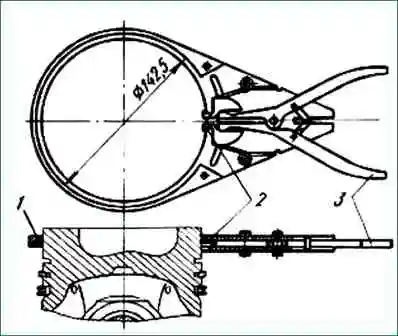
In order to install the piston assembly with piston rings and connecting rod into the cylinder liner, pre-compress the rings by sinking them into the piston grooves.
To compress the rings, use a mandrel (Fig. 8) with a conical inner surface and a collar that allows the mandrel to be correctly centered on the cylinder liner.
Having installed the piston in the mandrel, upset it in the cylinder liner.
When assembling the piston with the connecting rod and installing them on the engine, fulfill the following requirements:
- 1. The piston and sleeve must be of the same size groups.
- 2. Install the compression rings with the stamp “up” to the piston bottom.
- 3. Separate the locks of adjacent piston rings in opposite directions in the plane of the piston pin.
- 4. Install the piston so that the offset combustion chamber in the piston points into the engine, towards the fuel pump.
Pistons with a central combustion chamber are used on engines with individual cylinder heads.
Install the piston in the sleeve so that the arrow on the piston is directed towards the camber of the engine, towards the fuel pump. In this case, the grooves on the piston bottom for the valves will be shifted relative to the center of the cylinder towards the exhaust manifolds.
- 5. The mating marks on the connecting rod and the cap must be the same.
- 6. Dirt, burrs and nicks on the splines of the connecting rod and cap are not allowed.
- 7. Lubricate the threads and bearing ends of the heads of the connecting rod cap bolts with engine oil and tighten in two steps, starting with the long bolt, first with a torque of 100 Nm (10 kgcm), finally with a torque of 200 - 220 Nm (20 - 22 kgcm).
")

")
")
")
")
")
")
")