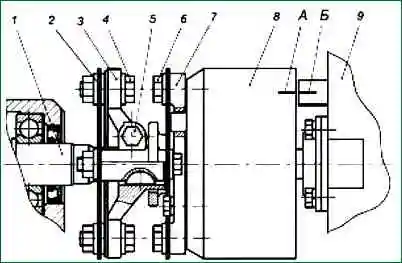
Install the driven coupling half (Fig. 1, 2) on the advance clutch (damper clutch) and fasten with bolts
Turn the coupling so that the bosses of the driven coupling half are in a horizontal position, and the mark on the end of the coupling is in the indicator zone
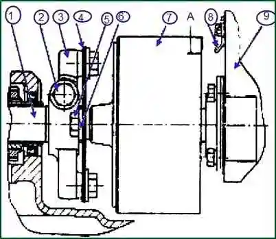
Install the coupling half flange assembly with the driving half coupling and plate packs on the drive shaft, while the protrusion "a" on the coupling half flange must be on the left side when looking at the drive from the fan side.
Install the high pressure fuel pump with advance clutch (damper clutch) assembly to the engine and secure it with bolts.
Before tightening the drive pinch bolt and after setting the injection advance angle, adjust the flatness of the plate packs by moving the coupling half flange along the drive shaft.
Install the fuel pump on the engine block in a vertical position, tighten the fastening bolts evenly, avoiding blockage of the pump.
The final tightening torque of the pump mounting bolts is 30-40 Nm (3-4 kgf.m).

Connect the pump sections to the injectors with the high pressure fuel lines in the order shown in fig. 3.
Adjust the fuel injection advance angle. We look at the article - How to adjust the fuel injection of a YaMZ-238 diesel engine
Check the presence of oil in the housings of the high-pressure fuel pump and regulator, if necessary, add oil to the level of the hole for the oil drain pipe.
Connect the oil inlet and outlet pipes and fuel lines.
After starting the engine, adjust the minimum idle speed of the crankshaft as follows:
- 1. After loosening the lock nut, unscrew the buffer spring housing by 2-3 mm.
- 2. Using the minimum speed limiter bolt (the control lever must rest against this bolt), adjust the minimum idle speed until small fluctuations in the engine speed occur.
When the bolt is screwed in, the engine speed increases, when it is screwed out, it decreases.
- 3. Screw in the buffer spring housing until the speed instability disappears. It is strictly forbidden to screw in the body of the buffer spring until its end is aligned with the end of the locknut.
After adjustment, lock the minimum speed bolt and buffer spring housing with nuts.
The minimum idle speed can also be adjusted on a new engine during the initial period of its operation.
It is strictly forbidden to violate the factory setting of maximum speed without subsequent testing on the stand during operation.
")

")
")
")
")
")
")
")