Before starting the adjustment, flush the oil chamber of the pump and regulator with clean diesel fuel and fill with fresh engine oil up to the level of the drain hole. For the duration of the test, plug the drain fitting
It is recommended to adjust high-pressure fuel pumps at the stands of Motorpal, Friedman-Mayer and other stands of similar designs.

The stand for adjusting high pressure fuel pumps must be equipped with:
- - a mechanism that provides a stepless change in the frequency of rotation of the drive shaft in the range from 0 to 1500 min -1
- - a device for installing and fixing the tested pump assembly with a speed controller, a fuel injection advance clutch and a fuel priming pump;
- - fuel tank, coarse and fine fuel filters;
- - a fuel system that provides fuel pressure at the pump head up to 2.3 MPa (23 kgf / cm 2);
- - a device for measuring and sampling portions of the fuel supplied by each section of the high pressure fuel pump;
- - a device for heating fuel and maintaining its temperature in the range of (32 ± 2) ºС;
- – a counter that sums up the number of plunger strokes, interlocked with a device for measuring and selecting fuel portions;
- – tachometer for setting the speed mode;
- – a dial for adjusting the alternation of feeds between pump sections;
- - flywheel on the pump drive shaft with a moment of inertia of 0.17 kg m 2 (1.7 kgf m.s 2);
- - the required number of pressure gauges, vacuum gauges and pipelines;
- - an additional system for supplying filtered oil to the fuel pump with adjustable pressure up to 0.4 MPa (4 kgf / cm 2) and a compressed air supply system with a device for smooth pressure control from 0 to 0, 15 MPa (from 0 to 1.5 kgf/cm 2) .
Equipment and devices of stands must meet the requirements of GOST 10578-95.
To control high-pressure fuel pumps, in addition to stands, the following equipment is required:
- - scales of the middle class of accuracy according to GOST 29329-92;
- - a device for controlling the beginning of the action of the regulator T 9597-111;
- - a device for controlling the amount of lift of the pusher T 9590-36.
Pump tests should be carried out on filtered diesel fuel grade L in accordance with GOST 305-82 or a process fluid consisting of its mixture with industrial oil in accordance with GOST 20799-88, aviation oil in accordance with GOST 21743-76 or lighting kerosene in accordance with TU 38.401-58 -10-90, having a viscosity of 5 to 6 mm 2/s (cSt) at a temperature of (20±5) ºС.
It is allowed to use a mixture of working fluids, consisting of 40% RZh-3 TU 38.101.964-83 and 60% RZh-8 TU 38.101.883-33, having a viscosity of 5 to 6 mm 2 /s (cSt) at a temperature of (20 ± 5) ºС.
The temperature of the fuel measured at the outlet connection of the stand with the fuel line to the tested pump, when controlling the magnitude and unevenness of the cyclic feeds, should be (32 ± 2) ºС.
Before installing the pump on the stand, check the axial clearance of the camshaft. If the gap exceeds 0.1 mm, adjust it with shims in the range from 0.01 to 0.07 mm.
When the bearing cap screws are tightened, the camshaft must turn freely in the bearings.
Checking and adjusting the fuel pump should be carried out with a bench set of injectors model 261-03С, having an effective flow area μf = 0.283 mm 2.
It is allowed to check and adjust the fuel pump with a working set of injectors.
Each injector must be assigned to the corresponding section of the fuel pump and subsequently installed in the engine cylinder that is connected to this section.
For the bench set of high pressure fuel lines, pipes with a length of (415 ± 3) mm should be used, the difference in the throughput of the fuel lines that make up the bench set should not exceed 1 mm 3/cycle.
Determine the throughput of the fuel line on one high-pressure section, with one nozzle and on one bench defoamer.
Check the adjusted fuel pump for leaks:
1. Drainage cavity, for which a tube with an internal volume of not more than 50 cm 3 (internal diameter not more than 8 mm) is hermetically connected to the oil drain plug.
Dip the free end of the tube into a vessel with fuel to a depth of no more than 50 mm. Seal the threaded hole of the regulator inspection hatch cover and the oil supply screw tightly.
To the screw-in drain supply compressed air at a pressure of 0.05 to 0.07 MPa (from 0.5 to 0.7 kgf / cm 2) in the th cavity of the fuel pump.
The fuel pump is considered fit if no air bubbles are observed in the vessel with fuel for 20 s;
2. Fuel pump connections. This test is carried out on a special bench equipped with a set of injectors with high pressure fuel lines. The working fluid is the same as for testing pumps.
Adjust the nozzle springs to the injection start pressure from 21.0 to 21.8 MPa (from 210 to 218 kgf / cm 2).
The outer surfaces of the fuel pump must be dry.
Test mode - nominal, the control lever of the speed controller must rest against the bolt for limiting the maximum speed.
Fuel pressure in the fuel pump line should be from 0.05 to 0.10 MPa (from 0.5 to 1.0 kgf / cm 2), fuel temperature from 50 to 60 ºС.
Test duration 45 min.
Fuel leaks through the seals and connections of the fuel pump are not allowed.
3. Tightness of fuel lines. To do this, plug the hole in the bypass valve screw and the fuel pump fittings.
Connect the bench fuel line to the fuel supply screw, remove the fuel pump cover and smoothly raise the fuel pressure in the line to 2 MPa (20 kgf/cm 2).
For 15 seconds, fuel leakage from under the screws, body plugs, plunger bushings, fittings and through the walls is not allowed.
When checking the fuel pump, the following is monitored:
- – geometric start of fuel injection by pump sections;
- – the amount and unevenness of the fuel supply across the pump sections.
The geometric start of pumping fuel by pump sections is determined by the moment when the fuel outflow from the fuel pump fittings stops, check and adjust at the position of the rail corresponding to the nominal supply, while the rail should protrude by (19 ± 1) mm from the end of the pump.
The start of pumping fuel by the first section of the pump must correspond to the lift of the pusher (4.5 ± 0.05) mm from the lowest position until the end of the plunger overlaps the inlet window of the sleeve.
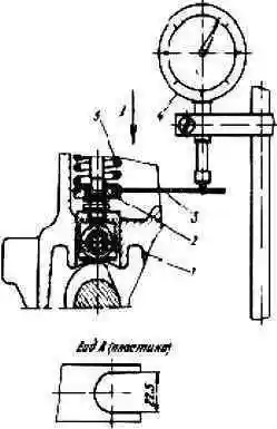
Measure the lift of the pusher with an indicator (Fig. 2).
At the moment the first section starts pumping fuel, the marks on the fuel injection start indicator and on the fuel injection advance clutch must match. The mismatch of the marks should not exceed 0.5º.
Pump sections should start pumping in the following order (in degrees - camshaft angles):
- Section #1 - 0° Section #4 - 180°
- Section #3 - 45° Section #5 - 225°
- Section #6 - 90° Section #7 - 270°
- Section #2 - 135° Section #8 - 315°
The deviation of the angles of rotation of the camshaft corresponding to the beginning of fuel injection by pump sections relative to the geometric start of fuel injection by the first section of the pump should be ± 30 minutes, no more.
The start of fuel injection is adjusted by the pusher bolt.
When the bolt is turned out, fuel starts to flow earlier, when it is screwed in, later. After adjustment, lock the adjusting bolt with a nut.
Check and adjust the amount and uniformity of the fuel supply; in the following order:
- 1. Check the pressure at the beginning of the opening of the discharge valves, which should be 1±0.15 MPa (10±1.5 kgf/cm 2).
The pressure of the start of opening of the discharge valves should be monitored by the moment the fuel begins to move from fuel lines with an internal diameter of (2 ± 0.05) mm or fittings with a gradual increase in fuel pressure at the inlet to the fuel pump, the rack position corresponding to the off fuel supply, and plugged hole in the bypass valve screw.
- 2. Check the fuel pressure in the line at the inlet to the fuel pump. The pressure should be 0.075±0.025 MPa (0.75±0.25 kgf/cm 2 ) when the control lever rests against the maximum speed limit bolt and the rated speed of the camshaft is 1030±10 min -1 for fuel pump 806.6-50 and 980±10 min -1 for fuel pump 807.6-50. If necessary, unscrew the bypass valve plug and adjust the opening pressure with washers.
- 3. Check the tightness of the discharge valves. In the position of the rail corresponding to the off supply, the discharge valves must not let the flow through for 2 minutes fuel under pressure 0.11±0.1 MPa (1.1±1 kgf/cm 2).
If there is a leak, replace the discharge valve kit.
- 4. Check the availability of the rail travel to turn off the feed. The rack stroke reserve (rack free play value - backlash) must be at least 1 mm when the regulator control lever rests against the minimum speed limiting bolt and at a camshaft speed of 450 to 500 min -1.
Adjustable with a backstage screw.
Protrusion of the yoke screw beyond the outer end of the regulator cover is not allowed.
5. Check the start of turning off the starting fuel supply at 230-250 min -1 when the control lever rests on the minimum speed limit bolt at the start of the rack movement.
If you need to increase the speed, remove the spring hook from the rack lever and screw it into the spring. To reduce the speed, the hook turns out.
After that, put the hook on the rail lever.
6. Check the value of the average starting fuel supply, which must be at least 230 mm 3/cycle at a camshaft speed of 80 ± 10 min -1.
It is regulated by the backstage screw only in the direction of increasing the fuel supply.
7. Check the frequency of rotation of the camshaft of the pump, corresponding to the beginning of the operation of the speed controller, fix on the tachometer at the moment the rail starts to move in the direction of turning off the supply, determined using an indicator device.
The start of the regulator action should occur at a camshaft speed of 1065 to 1085 min -1 for the fuel pump 806.6-50 and from 1025 to 1045 min -1 for the fuel pump 807.6-50.
Adjustment should be done with the maximum speed limit bolt.
8. Check the rotational speed corresponding to the complete shutdown of the fuel supply, fix it on the tachometer at the end of the fuel outflow through the injectors.
Complete shutdown of the feed should occur at a speed of 50-100 min -1 more than the speed of the camshaft, at which the regulator starts to operate.
If necessary, adjust by changing the position of the two-arm lever screw.
When screwing in the screw of the two-arm lever, the frequency of rotation of the camshaft, corresponding to the complete shutdown of the fuel supply, decreases, when screwed out, it increases.
At the same time, the start of switching off also changes, so its subsequent check and adjustment is necessary.
At the end of the adjustment, securely lock the screw of the two-arm lever and the bolt for limiting the maximum mode with nuts.
9. Check and, if necessary, adjust with the bench set of injectors model 261-03C with the regulator control lever resting against the maximum speed limit bolt, the average cyclic fuel supply, the increment in the average cyclic supply and the unevenness of the fuel supply by sections, which should be:

q - average cyclic fuel supply by the pump in nominal mode.
The value of the average cyclic feed is calculated as the sum of the feed of all sections divided by the number of sections.
The uneven fuel supply by sections is calculated by the formula:

- - qcmax – maximum cyclic fuel supply by sections, mm 3/cycle;
- - qcmin – minimum cyclic fuel supply by sections, mm 3/cycle.
10. Check the operation of the boost corrector, for this you need:
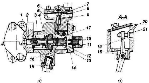
- - wash the mesh filter of the fitting 15 (Fig. 3) in clean gasoline and blow it thoroughly with compressed air;
- - clean the calibration hole in the corrector body with a soft wire with a diameter of 0.5 to 0.7 mm;
- – check the tightness of the corrector membrane cavity.
To do this, to the hole air under pressure 0.06 ± 0.01 MPa (0.6 ± 0.1 kgf/cm 2) in the cover of the membrane housing.
When the supply air duct is completely blocked, the pressure drop in the membrane cavity in 2 minutes should not exceed 0.01 MPa (0.1 kgf/cm 2);
- with the control lever resting against the maximum speed limitation bolt, set the rotation speed to 650 ± 10 min -1 and bring oil under pressure 0.275 ± 0.025 MPa (2.75 ± 0.025 kgf / cm 2).
To put the boost corrector into operation, turn off the fuel supply once using the rocker bracket, then move the rocker bracket to the on-feed position;
– check the value of cyclic feeds at different air pressures in the membrane cavity, which should be:

It is necessary to re-adjust the corrector if the measured values of cyclic feeds differ from those indicated.
Adjustment of the value of the cyclic fuel supply at an air pressure equal to zero, on the built-in boost corrector, is carried out by the adjusting bolt 21 (Fig. 3).
When screwing in a bolt, the feed rate increases, when screwing out, it decreases. After adjustment, lock the bolt with a nut.
Cycling at intermediate air pressures is controlled by the corrector spring housing.
When the spring housing is screwed in, the amount of fuel supply decreases, when it is turned out, it increases. After adjustment, lock the spring housing with a nut.
Before replacing a worn diaphragm (if necessary), measure the protrusion of the stem from the lower end of the nut on the diaphragm with the stem assembly.
After that, replace the membrane and assemble it with a rod with the same protrusion of the rod with an accuracy of 0.1 mm, while the sinking of the end of the spool 12 (Fig. 3) relative to the end of the piston 13 should be 0.2-0.9 mm in the absence of a gap between the end face of the piston and the body of the corrector.
When installing the boost corrector after dismantling (if it was necessary) on the regulator, move the pump rail to the extreme off position with the backstage bracket and install the boost corrector into the corrector housing, then release the bracket.
Check the adjustment of the boost corrector for the presence of a shutdown of the fuel supply by the regulator.
11. With the power adjustment screw, when the control lever rests against the maximum speed limitation bolt, limit the nominal cyclic feeds to the values that should be:

Securely lock and seal the power adjusting screw.
Check the travel reserve of the rack when the governor control lever rests against the minimum speed limit bolt and at a camshaft speed of 650 min-1.
The travel reserve of the rail must be at least 0.5 mm.
Check that the cyclic feed is turned off by the rocker bracket when turning 40-45 ° from the initial position.
The fuel supply from the injectors of all sections of the fuel pump at any speed of the camshaft must be completely turned off.
Install the caps on the fuel pump and regulator and seal them. Place a seal on the maximum speed adjustment bolt.
")

")
")
")
")
")
")
")