Removing the crankshaft position sensor
The sensor provides the controller with information about the rotation speed and angular position of the crankshaft.
The sensor is an inductive type, it reacts to the passage of the teeth of the timing disk, combined with the generator drive pulley, near its core.
The teeth are located on the disk at an interval of 6˚.
To synchronize with the TDC of pistons 1 and 4 cylinders, two teeth out of 60 are cut off, forming a depression.
When the depression passes the sensor, a so-called reference synchronization pulse is generated in it.
The installation gap between the core and the tops of the teeth should be within 1±0.4 mm.
When the timing disk rotates, the magnetic flux in the sensor's magnetic circuit — AC voltage pulses are induced in its winding.
Based on the number and frequency of these pulses, the controller calculates the phase and duration of the injector and ignition coil control pulses.
Removing and checking the sensor
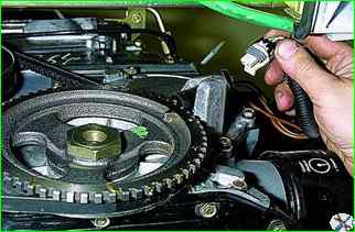
After turning off the ignition, disconnect the sensor connector.
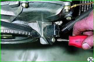
Use a Phillips screwdriver to loosen the sensor mounting screw.
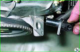
Remove the sensor from the camshaft drive cover bracket
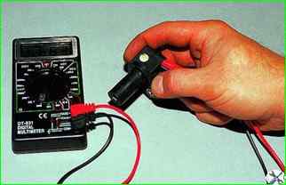
The resistance of a serviceable sensor should be within 550–750 Ohm
Install the sensor in the reverse order.
Removing the coolant temperature sensor
The sensor is a thermistor with a negative temperature coefficient, i.e. its resistance decreases with increasing temperature.
The controller supplies a stabilized voltage of +5 V to the sensor through a resistor (about 2 kOhm) and calculates the coolant temperature based on the voltage drop across the sensor. liquid, the values of which are used in most engine management functions.
If there is a malfunction in the coolant temperature sensor circuits, the engine management system malfunction indicator lights up, the controller turns on the cooling system fan to constant operation mode and calculates the temperature value using a bypass algorithm.
We carry out the work on a cold engine.
Partially drain the coolant.
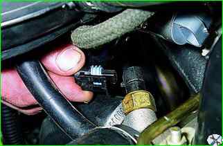
After turning off the ignition, disconnect the sensor connector.
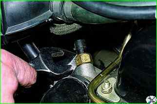
Using a 19 mm wrench, unscrew the sensor.
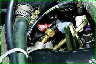
Take out the sensor together with the seal ring
To check, lower the sensor into a container with coolant and heat the container.
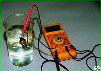
We monitor the temperature with a thermometer. We measure the resistance of the sensor at different temperatures
We install the sensor in the reverse order. The tightening torque of the sensor is 9–15 Nm. Top up the coolant to the norm.
Removing the throttle position sensor
The throttle position sensor is mounted on the throttle axis and is a potentiometric resistor.
A stabilized voltage of +5 V is supplied from the controller to one end of its winding, and the other is connected to the en with the "ground" of the controller.
The signal for the controller is taken from the third terminal of the potentiometer (slider).
By periodically measuring the output voltage of the TPS signal, the controller determines the current position of the throttle valve to calculate the ignition timing angle and the duration of the fuel injection pulses, as well as to control the idle speed regulator.
If the TPS or its circuits fail, the controller turns on the malfunction indicator and calculates the expected value of the throttle valve position based on the crankshaft speed and mass air flow.
Removing and installing the sensor
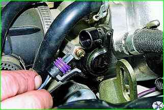
With the ignition off, disconnect the sensor's electrical connector
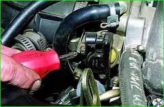
Using a Phillips screwdriver, unscrew the two screws securing the sensor to the throttle assembly
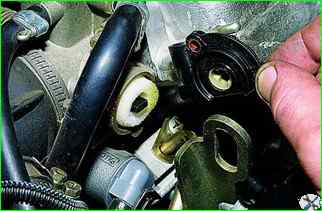
Remove the sensor.
Install the sensor on the throttle assembly in the reverse order.
In this case, the throttle valve should be in the closed position.
Removing the mass air flow sensor
The hot-wire mass air flow sensor (MAF) is located between the air filter and the air supply hose to the throttle assembly.
Depending on the air flow, the voltage of the sensor output signal changes from 1.0 to 5.0 V.
If the sensor fails, the controller calculates the mass air flow value by crankshaft speed and throttle valve position.
The MAF has a built-in air temperature sensor (ATS), the sensitive element of which is a thermistor installed in the air flow.
The sensor output signal changes in the range from 0 to 5.0 V, depending on the temperature of the air passing through the sensor.
If a malfunction of the ATS circuit occurs, the controller turns on the malfunction indicator and replaces the sensor reading with a fixed air temperature value (33˚C).
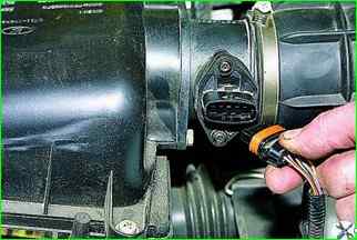
With the ignition off, disconnect the sensor's electrical connector.
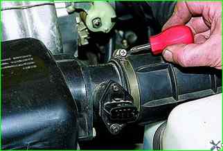
Using a Phillips screwdriver, loosen the clamp securing the supply hose and remove it from the mass air flow sensor pipe.
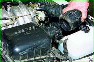
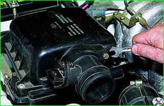
Using a 10 mm wrench, loosen the two bolts securing the sensor to the air filter housing
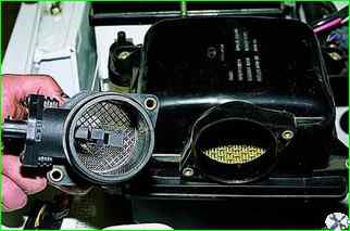
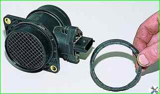
Removing the mass air flow sensor and the sensor seal
Install the sensor in the reverse order. Tightening torque of bolts 8–11 Nm.
Removing the knock sensor
The knock sensor (KS) is attached to the front upper part of the cylinder block.
The piezoceramic sensitive element of the sensor generates an AC voltage signal, the amplitude and frequency of which corresponds to the parameters of engine vibrations.
When detonation occurs, the amplitude of vibrations of a certain frequency increases.
In this case, to suppress detonation, the controller adjusts the ignition timing.
Remove the generator.
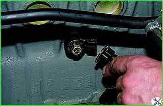
After turning off the ignition, disconnect the sensor connector.
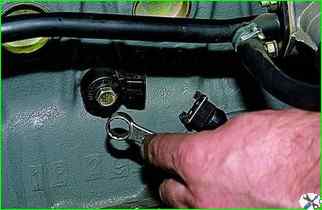
Using a 13 mm open-end wrench, loosen the bolt securing the sensor to the cylinder block and remove the sensor.
In photos 1–3, the intake pipe and air filter housing have been removed for clarity.
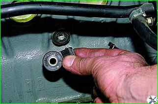
Before installing the sensor, clean the surface where it fits on the cylinder block.
Install the sensor in the reverse order. Tightening torque of the sensor mounting bolt is 20–25 Nm.
Removing the oxygen sensor
We carry out the work on an inspection pit or lift.
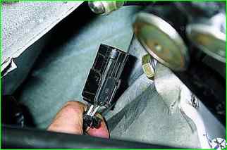
Disconnect the oxygen sensor connector.
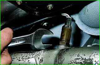
Using a 22 mm wrench, unscrew the sensor and remove it
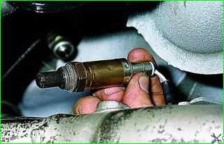
When installing the sensor, do not allow grease or dirt to get on the sensor tip with slots and on the wiring harness connector.
Tighten the sensor with a torque of 30–45 Nm.
Removing the speed sensor
We carry out the work on an inspection ditch or lift.
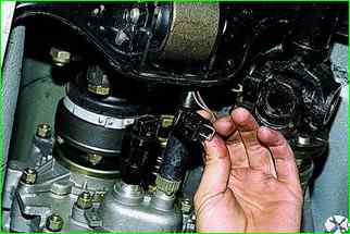
After turning off the ignition, disconnect the sensor connector
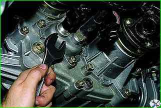
With the key "on 22" unscrew the speed sensor and remove it
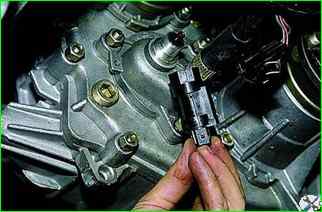
Install the sensor in the reverse order


