Removing the steering mechanism and adjusting the clearance in the worm bearings
We carry out the work on an inspection ditch or a lift.
Remove the bolt securing the lower universal joint fork of the intermediate steering shaft to the steering gear worm shaft (see Removing the steering column).
Hang out and remove the left wheel.
We press out the ball pins of the rods from the holes of the bipod: middle and side, article - “How to replace steering rods”
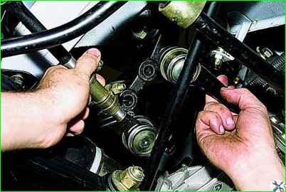
We move the rods down.
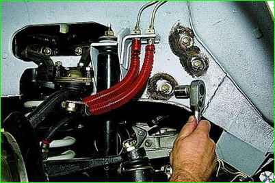
Using a 17mm socket, unscrew the nut of the bolt securing the steering gear housing to the left side member, holding the bolt from turning with a wrench of the same size.
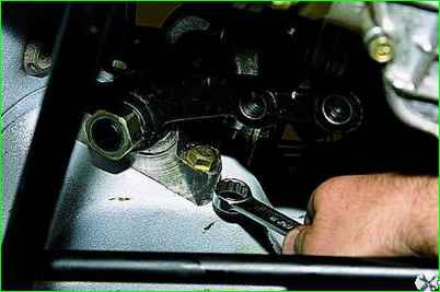
Remove the bolt.
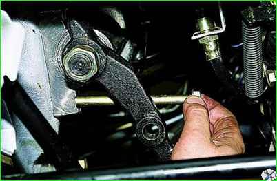
In the same way, unscrew and remove the other two bolts securing the steering gear housing.
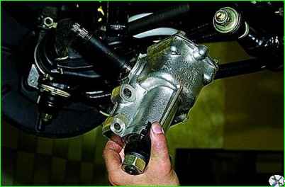
Remove the steering mechanism.
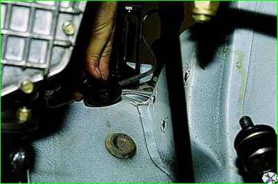
A rubber sealing sleeve is inserted into the hole in the front panel through which the worm shaft passes.
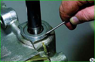
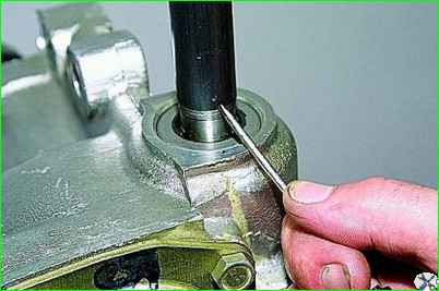
The clearance in the worm bearings is determined by the change in the distance between the end of the steering gear housing and the mark on the worm shaft when the shaft is turned in different directions.
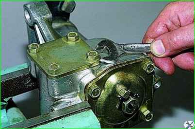
To adjust the clearance in the worm bearings, clamp the crankcase in a vice and use a 13mm wrench to unscrew the four bolts securing the bottom cover.
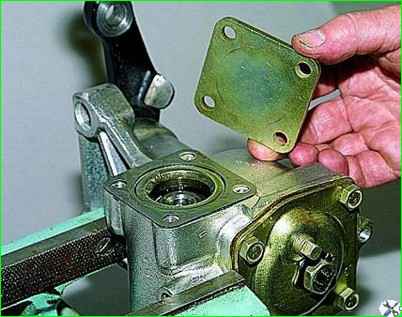
Remove the cover and shims.
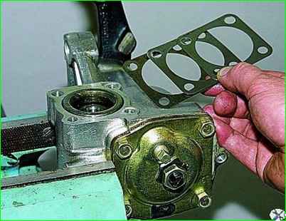
We reduce the gap in the worm bearings by removing the gasket or replacing it with a thinner one
Install the steering mechanism in reverse order, without fully tightening the nuts of the crankcase mounting bolts.
Attach the steering rods and intermediate steering shaft.
The assistant turns the steering wheel two or three times to the right and left until it stops. At the same time, we check the installation of the steering components in their standard places.
Tighten the nuts of the crankcase mounting bolts completely.
Removing the steering gear bipod
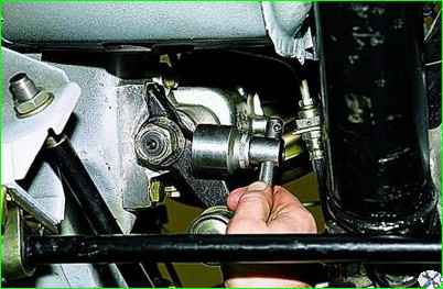
Use a 30mm socket to loosen the bipod fastening nut.
Remove the steering mechanism from the car
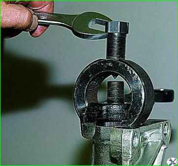
Use a puller to press the bipod off the shaft
In the absence of a puller, we dismantle the bipod using the impact method. We rest the bipod shaft against a wooden block.
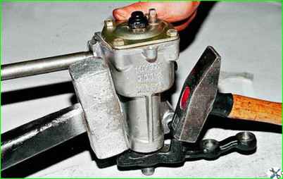
Use a sledgehammer to press on one bipod stop, and hit the second with a hammer.
In some cases you have to cut the bipod with a cutting machine.
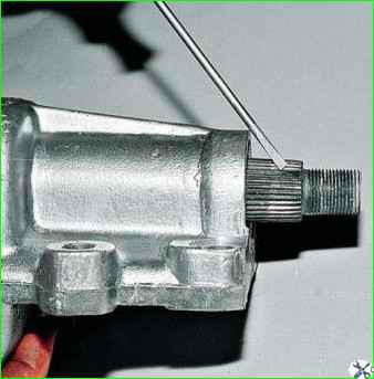
The bipod is installed on the conical splines of the shaft in only one position: when the double groove of the bipod and the double spline of the shaft coincide.
Adjusting the gap in the engagement of the roller with the steering gear worm
The adjustment is made when free play of the bipod of the steering mechanism is detected.
Before adjustment, you must make sure that there is no axial movement of the worm in the bearings.
The vacuum booster has been removed for clarity.
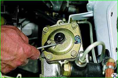
Use a slotted screwdriver to pry off the cap of the bipod shaft adjusting screw nut
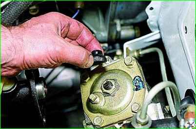
Remove the cap.
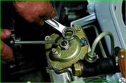
Using a 19mm spanner, loosen the nut of the bipod shaft adjusting screw and use a slotted screwdriver to pry off the lock washer.
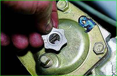
The lock washer fits into the groove of the adjusting screw with a tendril.
The washer is prevented from turning by a lug on the steering gear housing cover (the nut has been removed for clarity).
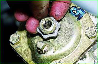
Lifting the washer (we release it from engagement with the tide)
Use a plate (bent at a right angle) to tighten the adjusting screw until the gap in the engagement of the roller with the steering gear worm is eliminated.
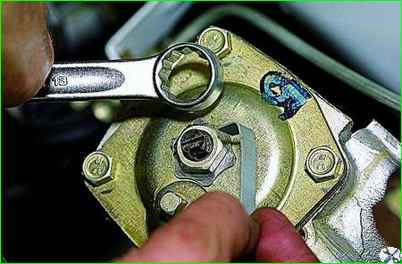
Holding the screw from turning with a plate, use a 19mm wrench to tighten the nut.
The steering wheel turning force when installing the front wheels on a smooth plate should not exceed 196 N (20 kgf).


