We repair the transfer case if there are any malfunctions
For disassembly you will need keys for 10, 13, 17, 24, 27, a screwdriver, a snap ring puller, a bearing puller, tweezers, a punch, a chisel, a vice with soft metal jaws
We remove the transfer case and clean it from dirt (removal of the transfer case is described in the article - Removal and installation of the Niva Chevrolet transfer case).
We loosen the tightening of the nuts of the three flanges of the transfer case shafts.
We remove the speed sensor drive housing.
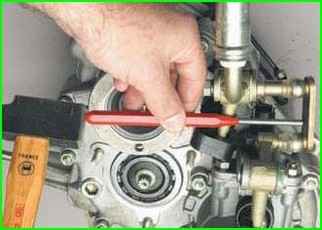
Disconnect the differential lock lever rod from the control lever fork axle.
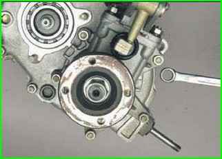
Using a 13 mm wrench, unscrew the five nuts securing the drive housing front axle.
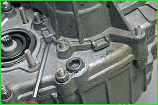
Pry off the crankcase lugs with a screwdriver
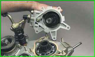
Remove it together with the front axle drive shaft
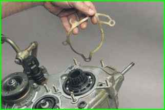
The connection is sealed with a gasket
Replace a heavily compressed or torn gasket by lubricating it with a thin layer of sealant
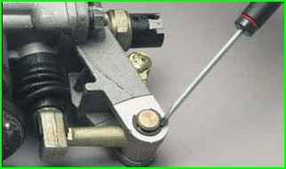
Pry off the locking washer of the locking axis with a screwdriver
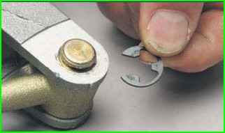
Remove the locking washer.
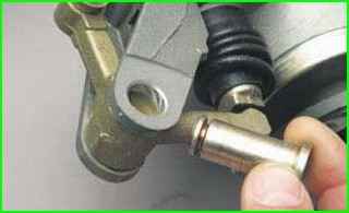
We take out the axle of the differential lock lever (if difficult, knock it out with a punch made of soft metal)
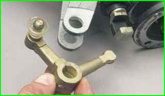
Remove the differential lock lever
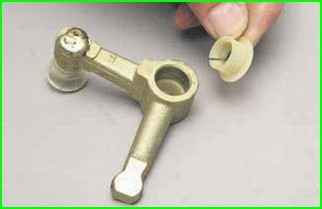
Two plastic bushings are installed in the hole in the lever
Unscrew the differential lock indicator light switch.
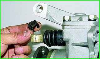
Remove the lever spring from the differential lock fork rod
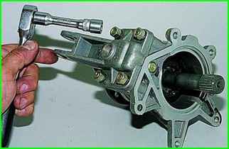
Using a 13 mm head, unscrew the four nuts securing the front axle drive housing cover.
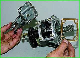
Remove the cover and gasket.
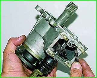
Remove spring and shake the retainer ball out of the housing socket
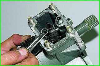
Using a 10 mm wrench, loosen the locking bolt of the differential lock clutch fork
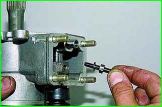
Remove the bolt with the spring washer
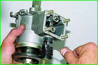
Use a screwdriver to pry off the protective cover of the differential lock fork rod
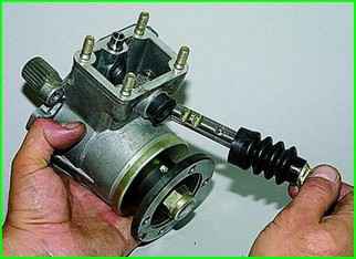
Removing the rod with the cover
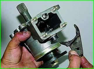
Removing the plug
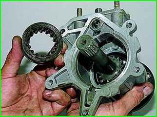
Remove the differential lock clutch
Unscrew the flange mounting nut and remove the washer.
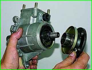
Remove the flange
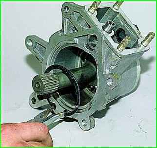
We squeeze with pliers, take out the retaining ring of the front axle drive shaft bearing
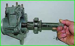
We take out the shaft assembly from crankcase
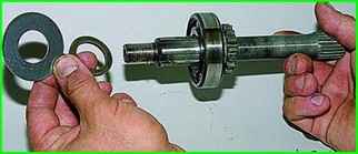
Remove the oil deflector washer and thrust ring from the front end of the shaft
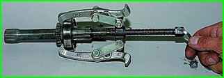
Having hooked the outer bearing ring with a three-jaw puller
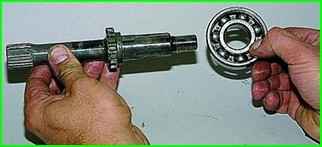
Pressing off the bearing
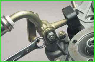
Using a 13 mm wrench, unscrew the control lever axle nut.
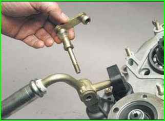
Remove the axle and rod from the hole in the lever.
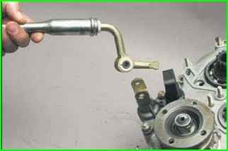
Remove the control lever.
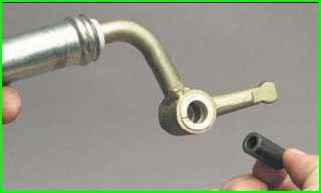
Remove the spacer sleeve from the lever hole
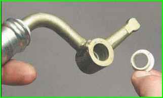
We take out two plastic teak bushings
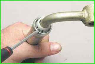
Use a screwdriver to remove the petals of the locking sleeve from the groove of the lever rod
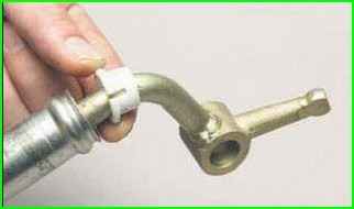
Removing the bushing from the lever rod
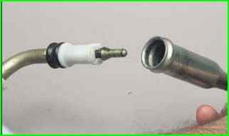
Removing the lever rod
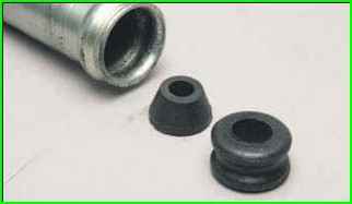
Prying with a screwdriver, we remove the rubber bushing and thrust pad from the rod hole.
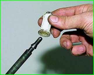
Having unclenched the petals of the distance bushing, we remove it from the lever
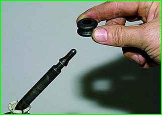
Removing the rubber bushing from the lever
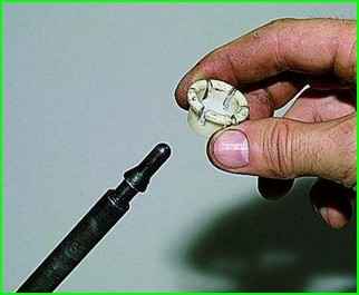
Remove the spacer sleeve.
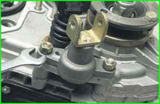
Using a 13 key, unscrew the two nuts securing the control lever bracket.
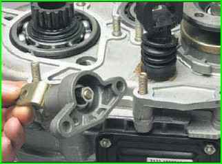
Remove the bracket together with the fork
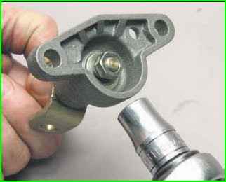
Holding the fork, use a 13 mm head to unscrew the fork axle mounting nut
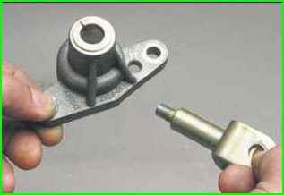
We take out the axle.
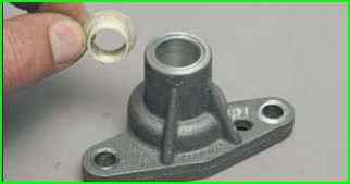
Two plastic bushings are installed in the bracket hole.
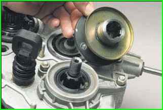
After unscrewing the drive shaft flange nut, remove the washer.
Remove the flange
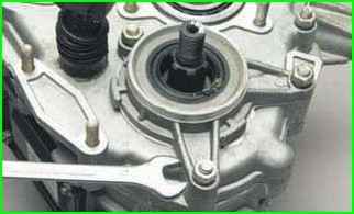
Using a 13 mm wrench, unscrew the three nuts securing the front bearing cover of the drive shaft.
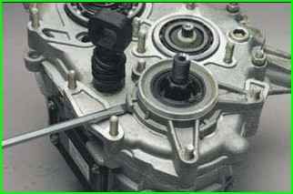
Using a screwdriver, pry off the cover lugs
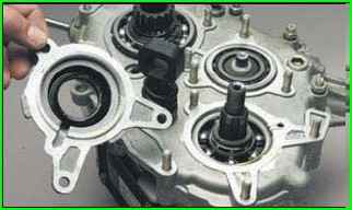
Remove the cover. The cover is installed with sealant
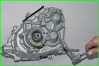
Using a 13 mm socket, unscrew the eight nuts securing the rear cover to the transfer case housing
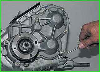
Use a screwdriver to pry off the cover
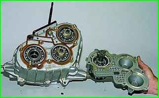
Removing the cover together with the rear axle drive shaft
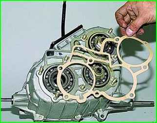
Removing the gasket.
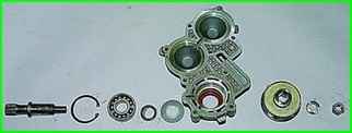
We take the rear axle drive shaft out of the rear cover and disassemble it in the same way as the front axle drive shaft.
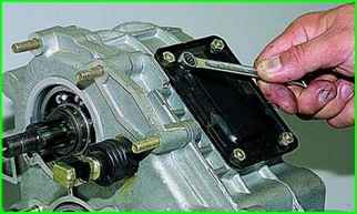
Using a 10 mm socket, unscrew the four nuts securing the hatch
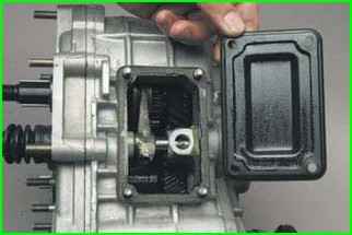
Remove the hatch
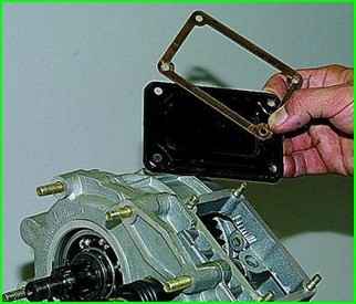
Remove the gasket
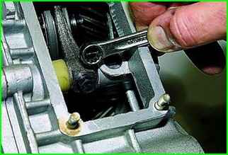
Inside the hatch, use a 10 mm open-end wrench to unscrew the bolt securing the fork to the rod.
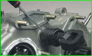
Use a screwdriver to move the piston rod cover.
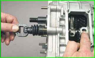
To prevent the ball and spring from popping out, cover the hole with your finger and gradually pull it out rod
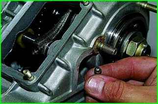
The locking ball falls out through the crankcase hole.
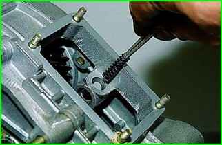
We take out the retainer spring with tweezers
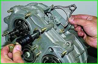
We remove the gear shift fork
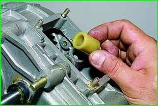
We take out the remote plastic bushing.
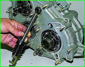
We take out the rod.
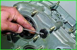
To replace the gearshift fork rod ring, use a screwdriver to pry off the sealing ring
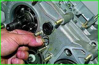
We take out the ring.
We also take out the sealing ring of the differential lock fork rod
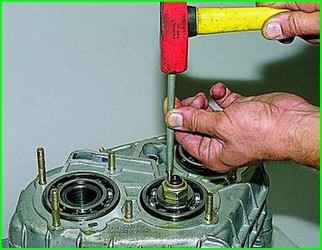
Unlock the nuts of the rear bearings of the drive and intermediate shafts.
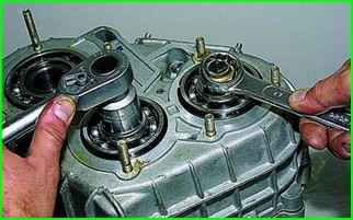
Use a 27 key to unscrew one of the nuts, holding the shafts from turning by the other nut with a key.
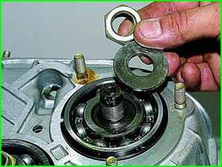
Remove the nut and washer
Insert the propeller shaft mounting bolts into the flange holes and put the flange on the splines of the transfer case input shaft.
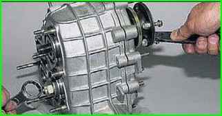
Unscrew the second nut, holding the shafts from turning with a mounting blade inserted between the bolts.
Remove the nut and washer.
Remove the drive shaft flange.
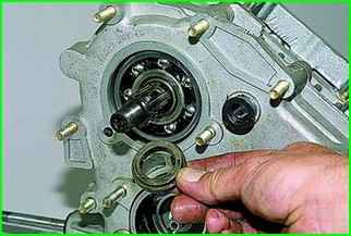
Remove the thrust ring of the front bearing of the drive shaft.
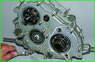
Using a 13 mm wrench, unscrew the three remaining nuts securing the front cover of the gearbox.
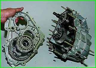
Remove the front cover of the transfer case and differential.
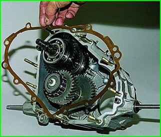
Removing the gasket from the studs of the transfer case housing
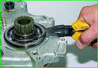
Using pliers, remove the installation ring of the front bearing of the differential housing
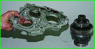
Disconnect the differential and the front cover of the transfer case
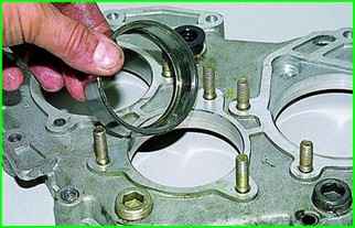
We knock out the outer ring of the front bearing of the intermediate shaft with a punch made of soft metal
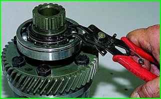
We use pliers to open the retaining ring of the front bearing of the differential housing
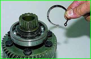
And remove the ring
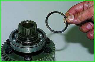
Remove the spring puck.
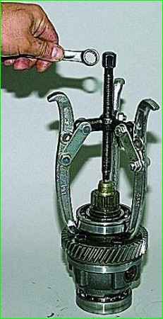
We install a suitable stop for the puller screw and a three-jaw puller in the hole of the front differential housing
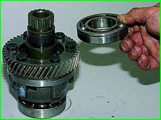
We press off the front bearing.
We also remove the rear bearing.
On the front and rear housings We apply marks to the differential so as not to disturb the balance during assembly.
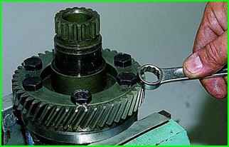
We clamp the differential housing in a vice and use a 17 mm open-end wrench to unscrew the six bolts holding the driven gear and the differential housings.
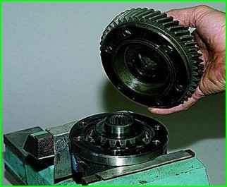
We separate the housings, while the driven gear remains on the front housing.
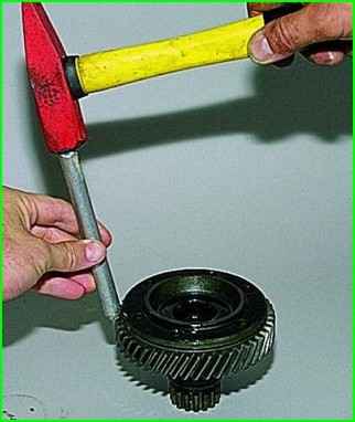
We knock the gear off the housing using a punch made of soft metal.
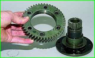
Disconnecting the driven gear and the front differential housing
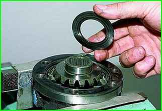
Remove the thrust washer from the front axle drive gear
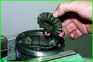
Remove the gear itself
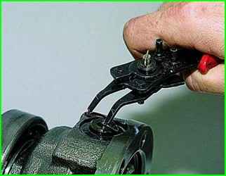
Using pliers, we unclasp the retaining ring of the satellite shaft and remove it
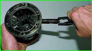
Using pliers, we hook another retaining ring and remove the satellite shaft.
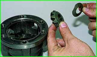
Remove the thrust washer and satellite from the rear differential housing.
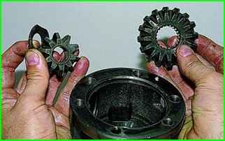
After removing the second satellite and its washer, we take out the rear axle drive gear.
To remove the primary and intermediate shafts, use pliers to remove the installation ring of the rear bearing of the drive shaft.
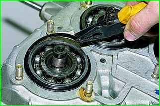
We also dismantle the ring of the rear bearing of the intermediate shaft.
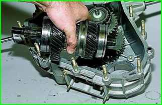
Removing the drive shaft from the crankcase
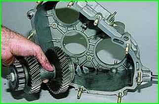
Removing the intermediate shaft
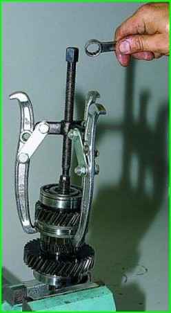
Clamp the splined part of the drive shaft in a vice with soft jaws and, having hooked the clutch of the puller with the grips, the gear shift clutch
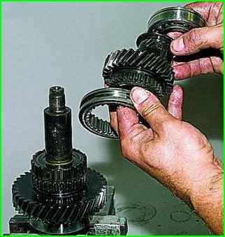
Remove the rear bearing, bushing, low gear and clutch.
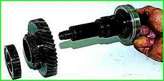
Remove the clutch hub and top gear from the shaft
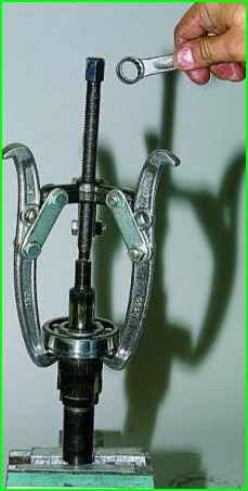
Using a puller, press off the front bearing of the drive shaft
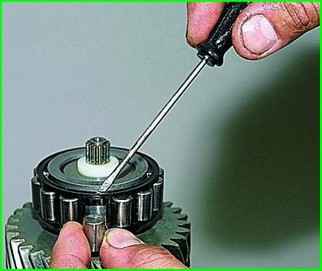
Using a screwdriver, remove the rollers from the front bearing of the intermediate shaft
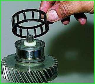
Remove the separator
Clamp the intermediate shaft in a vice with soft pads.
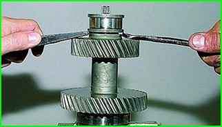
Pry up with two mounting blades, press off the inner ring of the front bearing
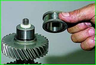
We remove it.
We also remove the rear bearing of the intermediate shaft
To check the technical condition of the transfer case parts, we thoroughly clean and wash them with kerosene.
There should be no cracks on the crankcases and covers of the box, and wear or damage (chips, dents, etc.) is not allowed on the surfaces of the bores for bearings.
Damage to the mating surfaces of the crankcases and covers can cause misalignment of shafts and oil leakage.
Minor damage is eliminated with a file, in case of significant damage and wear, replace the parts with new ones.
No damage is allowed on the working surfaces, threaded part and splines of the shafts.
There should be no scoring or signs of wear on the mounting surfaces of the gears.
Peeling or excessive wear of the gear teeth is not allowed.
Ball and roller bearings should not have damage on the raceways, separators, rollers or balls, as well as cracks and chips on the rings.
Radial clearances in bearings should not exceed 0.05 mm. Rotation of the bearing rings should be smooth, without jamming. Replace damaged bearings with new ones.
Forks must not be deformed or the rods must not stick in the housing holes.
Check for signs of sticking on the gearshift clutch hub and on the differential housing splines.
File off burrs and burrs. If the ends of the clutch teeth are crushed or damaged, replace the clutch.
Check the condition of the satellite axle surface and the holes in the differential housing; in case of minor damage, sand the surfaces with fine-grained sandpaper.
Check the condition of the surfaces of the axle drive gear journals and their mounting holes in the differential housings, as well as the condition of the surfaces of the gear support washers and the mating end surfaces on the housings and axle drive gears.
Before assembling the transfer case, clean the mating surfaces of the housings and covers from the remains of old gaskets and sealant.
Assemble the transfer case in the reverse order.
When assembling the center differential, align the marks on its housings.
Install the spring washer on the satellite axle from the side of the blind hole on the end of the axle.
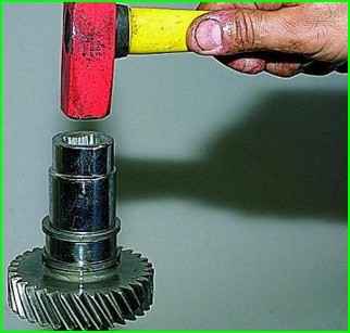
With pipe sections or tool heads of a suitable size we press on the inner ring of the front bearing of the intermediate shaft.
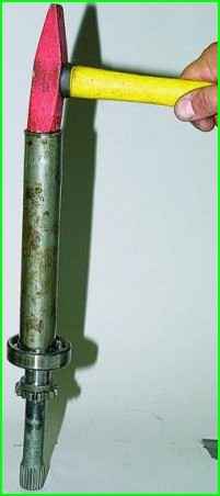
We press on the bearing of the front axle drive shaft (the pipe should rest on the inner ring).
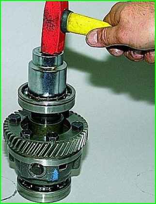
Press on the differential bearings
Press on the rear axle drive shaft bearing, the rear intermediate shaft bearing, the front and rear drive shaft bearings in the same way
Install the drive and intermediate shafts into the transfer case housing at the same time.
Apply a thin layer of silicone sealant to all sealing gaskets.
Having tightened the nuts of the rear bearings of the drive and intermediate shafts to the prescribed torque, lock the nuts by pressing their flanges into the grooves of the shaft tails.
After assembly, fill in the oil.
Tightening torques for fasteners of transfer case parts boxes
Part - Thread - Torque Nm (kgf.m)
- Nut for fastening the suspension bracket to the cushion axle М10х1.25 - 26.5-32.3 (2.7-3.3)
- Nut for fastening the suspension bracket to the body М8 - 15.0-18.6 (1.53-1.90)
- Nut for fastening the covers of the transfer case housing, front axle drive housing, speedometer drive housing, control lever bracket М8 - 14.7-24.5 (1.5-2.5)
- Differential lock switch М16х1.5 - 28.4-45.0 (2.9-4.6)
- Bolt for fastening the forks to the gear shift rods М6 - 11.8-18.6 (1.2-1.9)
- Bolt for fastening forks to differential lock rod - М12х1.25 - 11.7-18.6 (1.2-1.9)
- Bolt for fastening driven gear М10х1.25 - 66.6-82.3 (6.8-8.4)
- Nut for fastening rear bearing of drive shaft and rear bearing of intermediate shaft М18х1.5 - 96.0-117.6 (9.8-12.0)
- Nut for fastening flange of propeller shaft to drive shaft and to drive shafts of front and rear axles М16х1.5 - 96.0-117.6 (9.8-12.0)


