You will need: a portable lamp, a set of flat feeler gauges, a ruler, a caliper, a bore gauge, a micrometer, a scraper
After disassembling, thoroughly wash the parts with kerosene, blow and dry them with compressed air (especially the oil channels of the parts)
Inspect the block, especially carefully - the crankshaft supports.
Cracks in any place of the block are not allowed.
If there is a suspicion of cracks in the block (coolant got into the crankcase or oil into the coolant), check the tightness of the block on a special stand. Carry out the inspection in repair shops with the appropriate equipment.
Inspect the cylinders from both sides.
Scratches, burrs and cracks are not allowed.
When inspecting the cylinders, we recommend illuminating the cylinder mirrors with a portable lamp - this will make defects much more visible.
Use a bore gauge to determine the actual diameters of the cylinders.
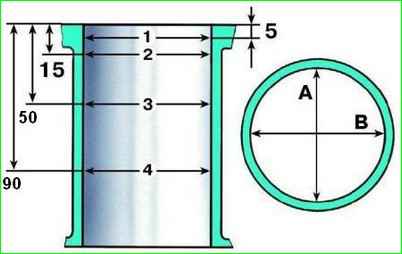
Measure the cylinder diameter in four belts (Fig. 1), located along the height of the cylinder at a distance of 5, 15, 50 and 90 mm from the plane of the parting with the block head.
In each belt, the diameter is measured in two mutually perpendicular directions (longitudinal and transverse).
Block cylinders are divided into five classes by diameter:
- A = 82.00–82.01 mm;
- B = 82.01–82.02 mm;
- C = 82.02–82.03 mm;
- D = 82.03–82.04 mm;
- E = 82.04–82.05 mm.
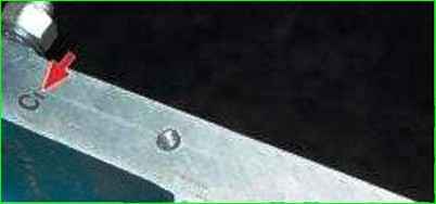
The class of each cylinder in the block in accordance with the manufacturer's documentation is marked with a stamp on the right side of the lower plane (the plane of the joint with the oil pan).
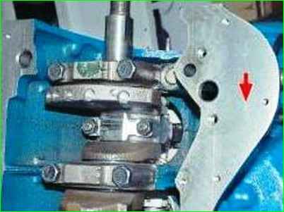
According to the manufacturer's documentation, a stamp with the conventional number of the cylinder block should be applied to the left side of the lower plane of the block.
The same number should be on all main bearing caps to indicate that the caps belong to this block.
In the area of the first belt (at a distance of 5 mm from the plane of the joint with the cylinder head), the cylinders are practically not worn out.
By the difference in size in the first and other belts, you can judge the wear of the cylinders.
If the maximum wear value is greater than 0.15 mm, bore the cylinders to the nearest repair size of the pistons (increased by 0.4 or 0.8 mm), leaving an allowance of 0.03 mm for the diameter under honing.
Then hone the cylinders, maintaining a diameter such that when installing the selected repair piston, the calculated gap between it and the cylinder is 0.05–0.07 mm.
Carry out defect detection, boring and honing of the block in workshops with special equipment.
Check the deviation from flatness of the surface of the joint between the block and the cylinder head.
Attach a caliper (or ruler) to the plane: in the middle of the block; in the transverse and longitudinal directions; along the diagonals of the plane.
In each position, use a flat feeler gauge to determine the gap between the caliper and the plane.
This will be the deviation from flatness. If the deviation exceeds 0.1 mm, replace the block.
Clean the piston bottom from carbon deposits with a scraper (can be made from an old file).
Clean the piston ring grooves from carbon deposits with an old ring, rotating it.
Inspect the pistons, connecting rods, and caps: they should not have cracks.
Inspect the liners.
If you find scratches, scoring, or peeling of the antifriction layer on the working surface, replace the liners with new ones.
All connecting rod liners are identical and interchangeable.
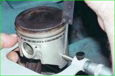
Measure the diameter of the pistons in a plane perpendicular to the axis of the piston pin, at a distance of 52.4 mm from the piston bottom.
Based on the results of the measurements, determine the clearance between the piston and the cylinder and, if necessary, select new pistons for the cylinders.
The calculated clearance between the piston and the cylinder (for new parts) is 0.05–0.07 mm.
It is determined by measuring the cylinders and pistons and ensure the installation of pistons of the same class as the cylinders.
The maximum allowable gap (when parts are worn) is 0.15 mm.
If the gap of a used engine exceeds 0.15 mm, it is necessary to select pistons for the cylinders: the gap should be as close as possible to the calculated one.
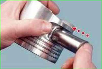
Insert a pin lubricated with engine oil into the piston boss hole.
The pin rotates freely in the piston bosses and in the upper head connecting rod.
By outer diameter, the pins are divided into three categories through 0.004 mm.
The category is indicated by paint on the end of the pin:
- 1st (blue mark) – 21.982–21.986 mm;
- 2nd (green mark) – 21.986–21.990;
- 3rd (red mark) – 21.990–21.994.
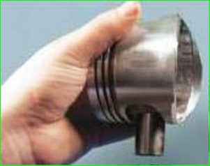
The pin should fit tightly, but without jamming, into the holes of the boss and connecting rod from the force of the thumb.
Turn the piston with the axis of the pin vertically.
The pin should not fall out of the boss.
Replace the pin that falls out of the boss with another one of the next category.
If the piston has a pin of the third category, replace the piston with the pin.
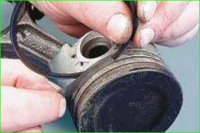
Check the height clearance between the piston grooves and the rings with a flat feeler gauge by inserting the ring into the corresponding groove.
The nominal (calculated) clearance is:
- – for the upper (first) compression ring 0.04–0.07 mm;
- – for the second compression ring 0.03–0.06 mm;
- – for the oil scraper ring 0.02–0.05 mm.
The maximum permissible clearances for wear are 0.15 mm.
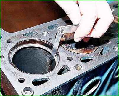
Check the gap in the ring lock with a flat feeler gauge, installing the ring into the cylinder to a depth of about 50 mm.
To install the ring without skewing, push the ring deeper into the cylinder with the piston.
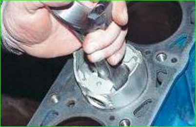
The gap is checked for rings inserted into a special gauge with a hole diameter equal to the nominal diameter of the ring with tolerance of ±0.003 mm.
The gap should be 0.25–0.45 mm for all new rings.
The maximum permissible gap for wear is 1.0 mm.
If there is no gauge, it is permissible to use the shown method. If the gap is insufficient, file down the mating surfaces of the ring.
If the gap exceeds the permissible value, replace the ring.
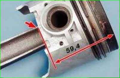
If possible, check the weight of the pistons: for one engine, they should not differ from each other by more than ±2.5 g.
You can adjust their weight by removing metal in the shown place on both sides of the piston.
The depth of metal removal should not exceed 4.5 mm, counting from the nominal piston height of 59.4 mm.
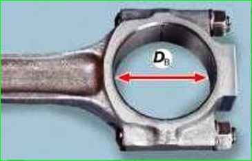
Use a bore gauge to measure the internal diameter Dв of the connecting rod seat assembled with the cover. Before measuring, tighten the connecting rod bolt nuts to the rated torque.
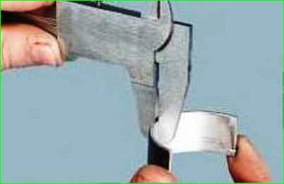
Measure the thickness T of the connecting rod bearings with a caliper
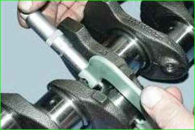
Use a micrometer to measure the diameter Dн of the connecting rod journals
Calculate the gap z between the connecting rod bearings and the crankshaft journals using the formula z=Dв–2T–Dн.
The nominal calculated gap is 0.02–0.07 mm.
The maximum gap is 0.1 mm.
If the actual calculated gap is less than the maximum, you can reuse the bearings that were installed.
If the gap is greater than the maximum, replace the bearings on these journals with new ones of nominal thickness (1.723–1.730 mm).
If the crankshaft journals are worn and reground to oversize, replace the liners with oversize ones (of increased thickness):
- «0.25» = 1.848–1.855 mm;
- «0.50» = 1.973–1.980 mm;
- «0.75» = 2.098–2.105 mm;
- «1.0» = 2.223–2.230 mm.
The nominal diameter of the connecting rod journals is 47.83–47.85 mm.
The journals are ground if they have nicks and scratches or wear (or ovality) is more than 0.03 mm, reducing the diameter in 0.25 mm increments so as to obtain (depending on the degree of wear) the following values:
- “0.25” = 47.58–47.60 mm;
- “0.50” = 47.33–47.35 mm;
- “0.75” = 47.08–47.10 mm;
- “1.0” = 46.83–46.85 mm. The designations "0.25" and others indicate how much the diameter of the crankshaft journals is reduced after grinding.
Inspect the upper and lower main bearing shells.
The upper shells of the 1st, 2nd, 4th and 5th main bearings have a groove on the inner surface (the lower ones do not).
The shells of the central (3rd) main bearing differ from the others in their greater width, in addition, its upper shell does not have a groove.
If there are scratches, scoring, or peeling of the antifriction layer on the working surface of the shells, replace the shells with new ones. It is prohibited to carry out any fitting operations on the shells.
Inspect the crankshaft. Cracks are not allowed.
There should be no scratches, nicks or grooves on the surfaces mating with the working edges of the seals. If detected, replace the shaft.
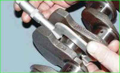
Use a micrometer to measure the outside diameter Dн of the main journals.
The actual clearance between the main bearing shells and the main journals of the crankshaft is determined using the method described for the connecting rod bearings.
The nominal calculated clearance is 0.026–0.073 mm. The maximum clearance is 0.15 mm.
If the actual calculated clearance is less than the maximum, you can reuse the liners that were installed.
If the clearance is greater than the maximum, replace the liners on these journals with new ones of nominal thickness (1.824–1.831 mm).
If the crankshaft journals are worn and ground to the repair size, replace the liners with repair ones (of increased thickness):
- «0.25» = 1.949–1.956 mm;
- «0.50» = 2.074–2.081 mm;
- «0.75» = 2.199–2.206 mm;
- «1.0» = 2.324–2.331 mm.
Nominal diameter of main journals 50.799–50.819 mm.
Junctions are ground if they have nicks and scores or wear (or ovality) is more than 0.03 mm, reducing the diameter in 0.25 mm increments to obtain (depending on the degree of wear) the following values:
- «0.25» = 50.549–50.569 mm;
- «0.50» = 50.299–50.319 mm;
- «0.75» = 50.049–50.069 mm;
- «1.0» = 49.799–49.819 mm. The designations "0.25" and others indicate how much the crankshaft journal diameter is reduced after grinding. The corresponding stamp is placed on the first cheek of the crankshaft, for example K 0.75; Ш 0.50.
Install the shaft with the outer main journals on the prisms and check with an indicator:
- – axial runout of the remaining main journals (no more than 0.03 mm);
- – axial runout of the mounting surfaces for the sprocket and bearing of the primary shaft of the gearbox (no more than 0.04 mm);
- – displacement of the axes of the connecting rod journals from the nominal plane passing through the axes of the connecting rod and main journals (no more than ±0.35 mm);
- – end runout of the flange at a diameter of 68 mm (no more than 0.025 mm). Checking the runout in a garage is almost impossible, so do it in workshops with special equipment.
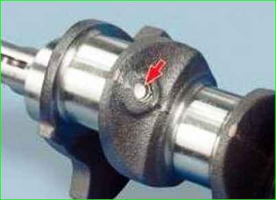
Inspect the plugs of the lubrication system channels.
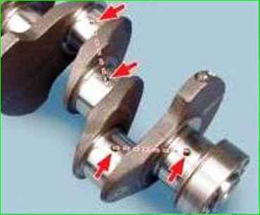
Check the reliability of their fit with a screwdriver, without applying significant force.
If the plugs are not installed securely, replace them.
Install the plugs on the UG-6 sealant and calk in three places.
We do not recommend opening the plugs yourself to clean the channels, which is certainly useful.
Contact workshops that have special equipment, or flush the channels without opening the plugs, for which pour gasoline into the radial channels (shown by arrows), having previously plugged them on one side with wooden plugs.
Wait for at least 20 minutes and flush the channels with gasoline, injecting it with a rubber bulb.
Remove the wooden plugs after flushing the connecting channels (shown in dotted lines). If necessary, repeat flushing until clean gasoline flows out.


