Some cars are additionally equipped with an air conditioning system, which is designed to reduce the temperature and humidity of the air in the cabin
The air conditioning system is turned on by pressing the air conditioning switch button located on the dashboard, while the indicator located in the switch button lights up.
Before turning on the air conditioning system, it is necessary to turn on the heater fan and move the temperature control handle to the left, to the blue sector.
Most of the air conditioning system units are located in the engine compartment.
In the car's cabin there is only an evaporator, located under the dashboard in place of the intermediate air ducts between the heater and its fan.
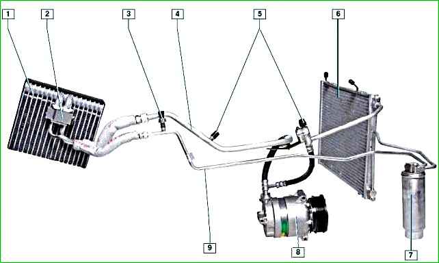
The evaporator serves for heat exchange between the air entering the car interior and the refrigerant circulating in the air conditioning system.
As it moves through the evaporator tubes, the refrigerant turns into steam.
The process is accompanied by heat absorption, the evaporator fins are cooled, the cold is “removed” from the fins and directed into the interior with the help of the heater fan, helping to lower the interior temperature in the interior.
The refrigerant, which is in a gaseous state, under low pressure enters from the evaporator into the compressor, which increases the pressure of the refrigerant.
The air conditioning compressor is installed on the right side of the engine cylinder block under the engine cooling system pump.
The compressor is driven by a poly V-belt from the auxiliary drive pulley.
In The compressor pulley has a built-in electromagnetic clutch that engages and disengages the compressor shaft from the pulley based on signals from the engine management system controller.
High-pressure refrigerant vapors from the compressor enter the condenser, which is located in front of the engine cooling system radiator.
Passing through the condenser cells, the refrigerant is cooled by the oncoming air flow and by the cooling system fans.
In this case, the refrigerant changes from a gaseous state to a liquid one.
Then the high-pressure liquid refrigerant enters the receiver, which is mounted under the right headlight in the cavity formed by the right wing, mudguard, front bumper and right bumper mudguard.
The receiver simultaneously performs several functions: as a filter, it cleans the refrigerant from impurities that have entered it; as a desiccant, it absorbs moisture condensing inside the air conditioning system and also serves as a reservoir for the refrigerant.
From the receiver, the refrigerant enters the reducer, located directly on the evaporator.
The reducer is a throttle valve, at the outlet of which the pressure and temperature of the refrigerant decrease sharply, as a result of which the refrigerant passes from a liquid to a gaseous state.
In this form, the refrigerant again passes through the evaporator, cooling the air entering the car interior.
From the evaporator, the refrigerant is sucked in again by the compressor, and the working cycle is repeated.
Valves for filling and releasing refrigerant from the air conditioning system are installed on the high and low pressure pipelines.
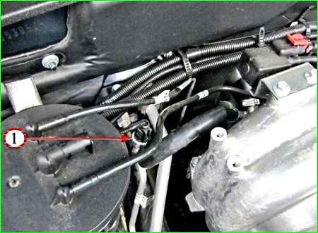
A refrigerant pressure sensor is installed on the high pressure pipeline.
The pressure sensor gives a signal controller, which controls the electric fans of the engine cooling system depending on the refrigerant pressure and the vehicle speed.
In addition, based on signals from the pressure sensor, the controller switches off the air conditioning compressor if the refrigerant pressure in the system is too low or too high.
A shut-off valve is installed under the pressure sensor in the fitting, which closes when the sensor is unscrewed, so when replacing the pressure sensor, there will be no refrigerant leakage from the air conditioning system.
The refrigerant in the air conditioning system is mostly under high pressure.
When working on depressurizing the air conditioning system, avoid getting it in your eyes, on your skin, or inhaling it.
Any work with refrigerant must be carried out only in a ventilated area.
When filling the air conditioning system, use only materials recommended by the manufacturer.
It is prohibited to carry out welding or soldering work on air conditioning system units.
Air conditioning system repair and maintenance work
Special equipment is used to search for leaks in the system, and a special contrast agent must be introduced into the system.
After removing the refrigerant from the system, it is imperative to pump out the air to remove any remaining moisture.
Before filling the air conditioning system, it is necessary to add a special oil recommended by the manufacturer.
The connection diagram of the car's air conditioning system is shown in Fig. 2
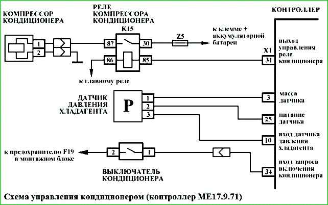
This air conditioning system uses an analog pressure sensor.
The pressure sensor is installed on the high-pressure pipeline.
A supply voltage of 5 V is supplied to the pressure sensor.
The output signal of the pressure sensor is directly proportional to the pressure applied to it, and changes linearly within the range from 0.25 V to 3.35 V when the pressure changes from 100 kPa to 2400 kPa.
By analyzing the signal from the pressure sensor received at the "X1/10" contact of the controller, the controller calculates the refrigerant pressure in the pipeline.
Based on these calculations, the controller decides whether to allow the air conditioner to turn on.
When the driver turns on the air conditioner switch located on the instrument panel, a request signal to turn on the air conditioner is sent to the "X1/34" contact of the ECM controller.
When receiving a request The controller adjusts the throttle valve opening angle to compensate for the additional load created for the engine by the air conditioning compressor.
The idle speed value of the crankshaft can increase to 1000 min -1. After that, the controller switches on the air conditioning compressor clutch via the relay.
Thus, the air conditioning compressor switches on under the following conditions:
- - more than 5 seconds have passed since the engine started;
- - the on-board network voltage does not exceed 16.5 V;
- - the throttle valve is open no more than 68%;
- - the driver turned on the air conditioning;
- - the refrigerant pressure in the high-pressure line is within a certain range.
When the air conditioner is turned on, the reduced performance of the electric fans of the engine cooling system is switched on, regardless of the coolant temperature.
The controller switches on the electric fans of the engine cooling system to maximum performance if the refrigerant pressure in the high-pressure line exceeds 1600 kPa and switches off when the pressure drops to 1300 kPa.
If the refrigerant pressure sensor is faulty, the controller turns off the air conditioner.
Possible malfunctions of the air conditioning system
Possible malfunctions
Methods of correction
When the air conditioner is on, the air in the cabin is not cooled
Insufficient charge of refrigerant in the air conditioning system, refrigerant leak, deformed or pinched pipes
The entire system needs to be checked
The heater fan motor is faulty, the fuse has blown or the relay is faulty.
Check the operation of the heater fan motor. Replace the blown motor protection circuit fuse and relay.
Loose compressor drive belt tension
Tighten the belt
Compressor clutch does not engage
Check the clutch engagement circuit. Replace the faulty clutch.
Air conditioner switch does not work
Replace the switch
The controller does not send a signal to the air conditioner compressor electromagnetic clutch engagement relay (the fuse has blown or the relay is faulty).
Replace the relay or fuse for protecting the electromagnetic clutch engagement circuit.
")

")
")
")
")
")
")
")