Purpose, design and operation of the EFU
The device is designed to facilitate starting a cold engine at air temperatures down to -25 °C, quickly return the engine to normal temperature conditions and reduce smoke that occurs in a cold engine.
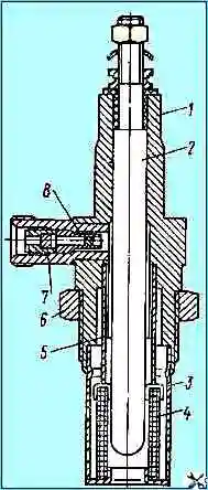
EFU glow plugs are screwed into the threaded holes of the intake manifolds.
The electromagnetic valve of the ECU is installed on the engine, the thermal relay is on the cab panel on the inside.
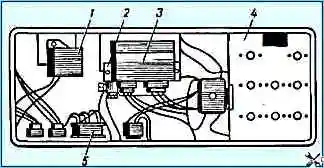
The ECU switch-on relay is located on the panel of the front part of the cab on the right side in the direction of travel of the vehicle (see Fig. 1).
The heater activation relay and the ECU activation contactor are in the cab behind the fuse panel.
When the engine starts, the fuel priming pump supplies fuel through the fine filter to the spark plugs.
The injection pump bypass valve and the jet valve of the fine fuel filter are closed, and fuel under pressure is supplied to the EPU spark plugs with a minimum delay from the moment the solenoid valve opens.
At a pressure greater than 25-45 kPa (0.25-0.45 kgf/cm 2), the jet valve opens, maintaining optimal pressure in front of the EFU spark plug jet for stable combustion of the torch.
The electrical circuit of the EFU system consists of a power button, a spark plug relay, a thermal relay, an electromagnetic fuel valve, two pin spark plugs, and a control lamp.
The electric torch device works as follows: when the spark plug button is turned on, the voltage from the batteries through an ammeter, relay and thermal relay is supplied to the ECU and pin spark plugs. At the same time, they warm up.
Simultaneously with the heating of the spark plugs, the thermal relay heats up and is activated, including the electromagnetic fuel valve and the control lamp of the unit.
In this case, the valve opens access to the spark plugs, and the lighting of the control lamp indicates that the device is ready to start the engine.
In addition, when the spark plug button is turned on, voltage is supplied to the relay, which breaks the generator excitation winding circuit, which is necessary to protect the spark plugs from the voltage generated by the generator when the engine reaches a stable mode accompanied by the operation of the ECU.
The current consumed by the electric torch device does not exceed 24 A. This value of current consumption does not have a negative effect on the subsequent starter discharge of the batteries.
The resistance of the thermal relay spiral is selected in such a way that a voltage of 19 V (nominal voltage of the spark plugs) is provided at the spark plug terminals.
When the engine starts, the thermal relay is bypassed, i.e. voltage is supplied to the spark plug terminals, bypassing the thermal relay spiral, since when the engine cranks with the starter, the voltage at the battery terminals decreases.
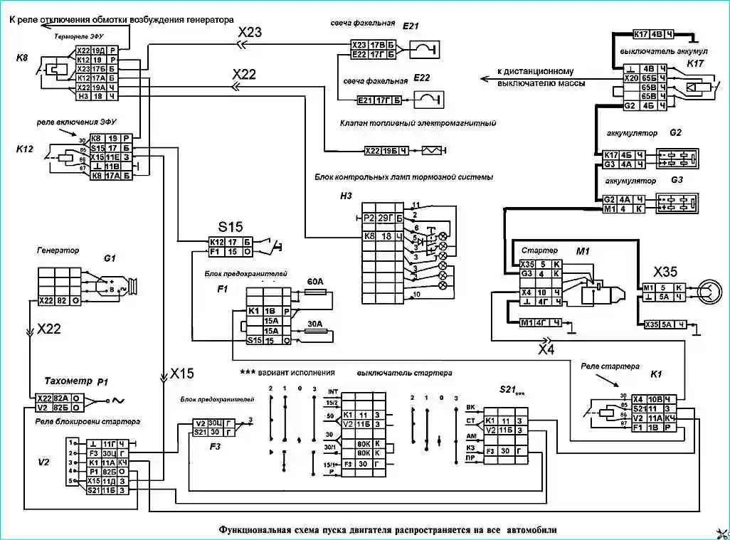
Figure 3 shows a functional diagram of starting the engine of KamAZ family vehicles.
Checking the functionality of the EFU
The operation of the EPI should be checked with serviceable and charged batteries in the following order:
- - check the serviceability of the ECU indicator on the instrument panel in the cockpit (by pressing the control button);
- - turn on the EPI and determine the time when the EPI is turned on before it lights up signaling device.
To turn on the EFU for the first time, it should be 50-70 C at an air temperature above zero, and 70-110 C at a temperature below zero.
When the EPI is turned on again, the time the indicator lights up is reduced, therefore, to obtain a reliable value, it is necessary to allow the thermostat to cool to ambient temperature:
- - check for the presence of a torch flame in the intake manifolds.
To check the torch you need:
- - unscrew the spark plugs from the manifolds, connect fuel pipes and electrical wires to them;
- - ensure a reliable connection of the spark plug housings to the ground and make sure that the terminal is isolated from the ground;
- - turn on the ECU, and after the indicator lights up, use the starter to turn the crankshaft. If there is no flame, replace the faulty spark plug.
Determine the performance of relay 4 for turning on the EPI in the following order:
- - disconnect any wire from terminal “K” of the additional starter relay;
- - press the ECU power button two or three times for no more than 1 s, turn the instrument and starter switch key to position II (far right position). If the relay is working properly, you should hear characteristic clicks;
- - turn off the EFU and connect the wire to terminal “K”.
Determine the performance of the OVG shutdown relay as follows:
- - press the ECU button and start the engine with the starter. When the engine speed changes over the entire range, the ammeter needle should show a discharge current of about 30 A. Stop the engine and only then release the ECU button;
- - start the engine again and make sure that the generator is charging.
EFF failures
Voltmeter needle at the lower limit of the scale:
- - Closing the thermal relay spiral or electrical wires
- - Short circuit of the spark plug to ground - If the spark plugs are in good condition, disconnect the wire from the thermal relay connecting it to the ECU power button.
The absence of a change in the arrow readings indicates the closure of the thermal relay spiral. In this case, the thermal relay should be replaced.
If the thermal relay spiral is intact (determined by touch) and the position of the arrow does not change when the wires are disconnected from the spark plugs, then this indicates a short circuit in the electrical wires.
Remove short circuit.
Disconnect the wire from the left spark plug terminal, eliminating contact of the tip with ground, and turn on the EPI again.
When the arrow goes beyond the scale, disconnect the wire from the right spark plug terminal.
The absence of the arrow going beyond the scale indicates the closure of the right candle.
Replace the failed spark plug.
After eliminating the short circuit, it is recommended to check the condition of the insulation of the electrical wires, the operability of the thermal relay and the ECU turn-on relay, and if a short circuit occurs when starting the engine, the operability of the shunt relay
The voltmeter reading does not change:
Thermal relay spiral burnout - Turn on the ECU and check the voltage at the thermal relay terminals.
The absence of voltage at the terminal on the side of the plug connection and the presence of voltage at the other terminal indicates burnout of the spiral.
Replace the thermostat
Burned spark plugs or lack of contact in the circuit - Turn on the EPI and check the presence of voltage at the terminals of each EPI product, starting with the torch spark plugs.
The presence of voltage at the terminal of the right spark plug indicates burnout of the spark plugs.
Replace the spark plug and restore contact
One of the spark plugs has burned out - Turn on the ECU for 10-15 s, then replace the cold spark plug
No candle torch:
No fuel supply to the spark plug - Loosen the fuel supply fitting on the spark plug.
Turn on the ECU and after the indicator lights up (opening of the solenoid valve), turn the crankshaft using the starter.
If fuel does not leak through a loose threaded connection of the fitting when the valve is open, troubleshoot the fuel supply system
Fuel not passing through the spark plug - Remove the spark plug from the manifold.
Rinse and blow out the nozzle, fuel filter and fuel supply cavities with compressed air.
Check for presence of torch flame
Leaking fuel supply system - Eliminate leakage
Signs of device failure may include:
- the ammeter needle is off scale;
- the ammeter needle does not deviate;
- The ammeter needle shows half the discharge current; lack of flame torch.
The most typical failures include:
- short circuit of spark plugs to ground, short circuit or burnout of thermal relay coil;
- burnout of spark plugs or lack of contact in the circuit;
- s fuel system.
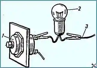
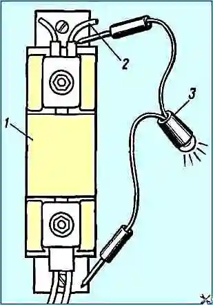
The EPI power button is checked using a test lamp by connecting it to the terminals one by one (Fig. 4).
When the lamp is connected to pin 15, the lamp should light up; when connected to pins 19 and 17, the lamp should not light up (when the EPI power button is released).
When the button is pressed, there should be voltage on all three terminals.
The ammeter is checked in the same way.
To check the EPU thermal relay, connect a test lamp to pin 19: the lamp should be on.
Then check the serviceability of the thermal relay winding by connecting the lamp to terminal 17A or 17B (Fig. 5): the lamp should be on (the EPI power button is pressed).
To check the serviceability of the thermal relay contacts, you need to connect the lamp to pin 18 (or 19A), press the ECU power button. A working relay should turn on the lamp in 75-110 s.
To check the EPU relay, you need to connect a test lamp to pin 17B of the EPU relay (the EPU power button is pressed).
The lamp should light up; if it doesn’t light up, it means the wire is faulty.
Then they check the serviceability of the relay contacts, for which they connect the lamp to terminal 17A (the ECU power button is pressed): the lamp should be on.
To check the solenoid fuel valve, you need to connect the wire from the “+” batteries to the valve terminal. In this case, a click should be heard when the valve operates.
To check the spark plugs, you need to unscrew the spark plugs, install them on the car body and turn on the ECU button. After 75-110 seconds, the candles should glow.
Repair
Electric torch device products cannot be repaired; If a product failure is detected, replace it.
To check the fuel supply to the spark plugs, disconnect the fuel line from the spark plugs and bleed the engine supply system with fuel using a manual fuel priming pump.
Then open the solenoid valve by applying voltage to the valve plug from the engine compartment lamp wire plug. In this case, fuel should appear from the disconnected fuel line.
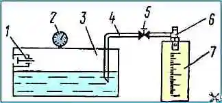
Determine the throughput of the spark plug on domestic SDTA-Z (KI-22201) and other stands that allow you to smoothly regulate the fuel pressure.
At an excess pressure of diesel fuel of 73.6 kPa (0.75 kgf/cm 2) and a temperature of 15-25°C, the throughput of the spark plug should be 5.5-6.5 cm 3/min.
Make measurements after first pouring fuel onto the spark plug for 20-30 seconds.
If the specified stands are missing, assemble the installation according to the diagram in Fig. 6.
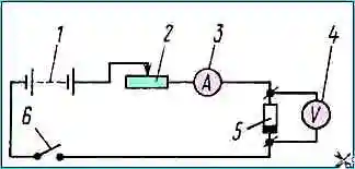
To determine the amount of current consumed by the spark plug, assemble a circuit (Fig. 7) that allows you to have a DC output voltage of 19 V.
Maintain the voltage with rheostat 2. At this voltage, the current consumption a minute after turning on the spark plug should be 11-11.8 A.
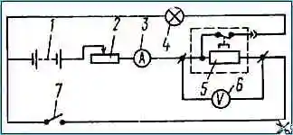
To check the parameters of the thermal relay, assemble the circuit shown in Fig. 8. Install the thermal relay on a horizontal surface with the protective screen facing up.
Set and maintain the nominal current value of 22.8 A passing through the relay with rheostat 2.
The time before closing the contacts and keeping them in the closed state is determined by the lighting of indicator lamp 4.
To do this, connect one wire of the control lamp to the thermal relay plug, and the second to a DC source (battery).
The time from the moment the current is turned on until the thermal relay contacts close (the control lamp lights up) at an ambient temperature of 15-25 ° C should be 55-65 s, and the contact holding time (the control lamp lights up) after disconnection should be at least 45 s.
Check the tightness of the solenoid valve by supplying compressed air under a pressure of 147 kPa (1.5 kgf/cm 2) to the valve inlet channel.
When immersing the valve in water, do not air bubbles are released.
")

")
")
")
")
")
")
")