The gear shift drive consists of a gear shift lever, a ball joint, a rod, a gear selection rod, and gear selection and shift mechanisms
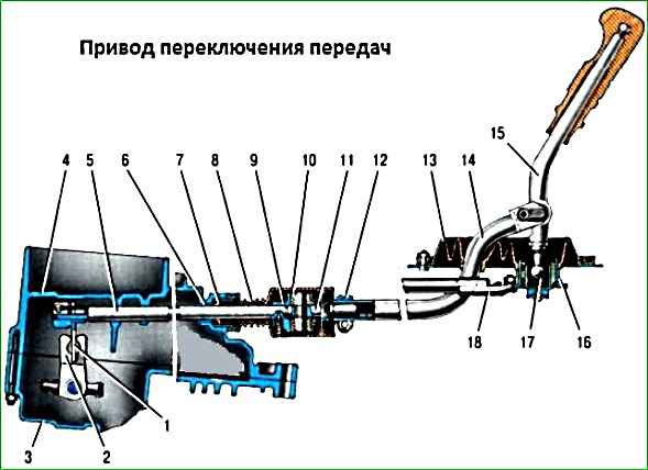
To prevent spontaneous gear disengagement due to axial movement of the power unit on its stops when the vehicle is moving, a jet thrust 18 is introduced into the gearbox control drive, one end of which is connected to the power unit, and the sleeve 16 of the ball joint of the gearshift lever 15 is attached to the other end.
A lever 1 is fixed to the inner end of the rod 5, which acts on the three-arm lever 2 of the gear selection mechanism.
This mechanism is made as a separate unit and is attached to the plane of the clutch housing.
The most typical defects as a result of operation are:
- - wear or breakage of plastic parts in the gearbox control drive;
- - deformation of the gearshift mechanism control drive rod or jet thrust;
- - Insufficient gear engagement due to incorrect adjustment of the gearbox control drive.
Replacing the gearshift lever axle bushings
Removing the floor tunnel trim
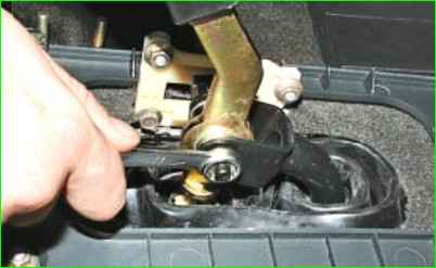
Using a 13 key, unscrew the gearshift lever axle mounting nut
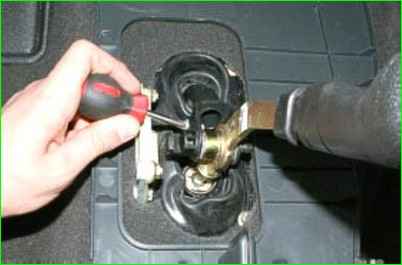
Unscrew the screw securing the lever axis stop
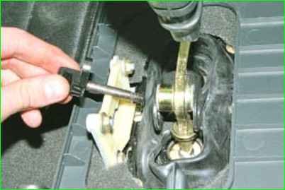
Pressing the lever to the side, remove the lever axis assembly with the stop
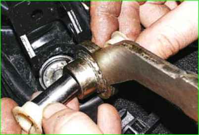
We remove the lever from the traction fork, take out two plastic axle bushings and a spacer bushing
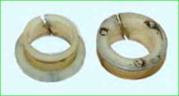
The plastic bushings have a cut
We install all the parts in the reverse order.
Before installation, lubricate the plastic bushings with lithol or other consistent lubrication
If there is a problem installing the lever axis, then in order to be able to move the lever further to the side, you need to remove the protective plate from below
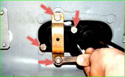
Unscrew the two nuts securing the protective plate and the two bolts securing the reaction rod.
After installing the axis, install the reaction rod in place and adjust the gear shift mechanism drive.
Repairing the gear shift lever
The gear shift lever should rotate freely in the ball joint without jamming hinge.
If this is not the case, then you need to check and replace the ball joint and spherical washer.
If after pressing down to the stop the lever does not completely return to its original position, you need to check and, if necessary, replace the spring.
Remove the floor tunnel lining
Remove the lever axis, plastic bushings, as described above
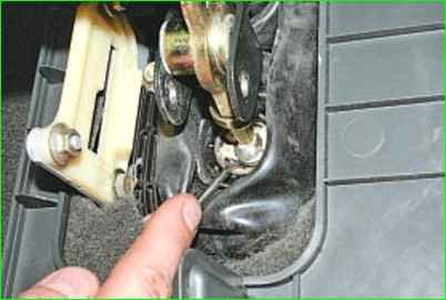
Pry off the retaining ring with a screwdriver
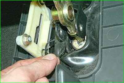
Remove the retaining ring
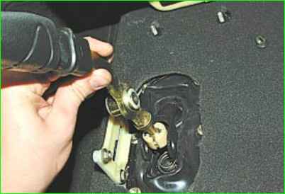
Remove the ball joint with the lever from the cage
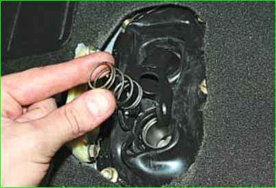
Removing the spring from the clip
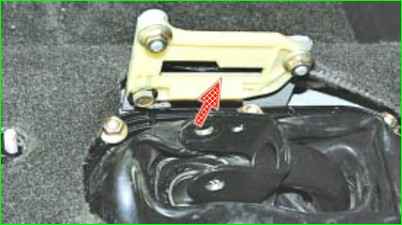
Inspecting the reverse lock bracket lining
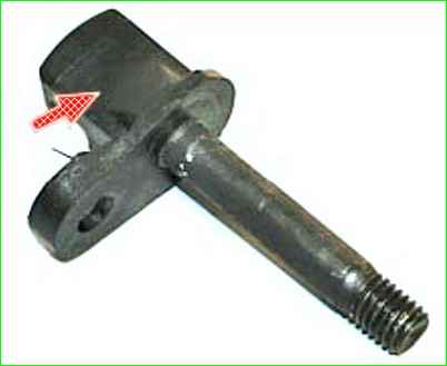
Inspect the plastic axle stop
Replace parts if they are broken or show signs of wear
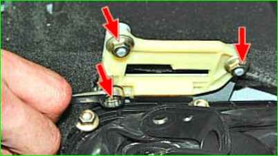
To remove the cover, unscrew the two nuts and unscrew one bolt that secures it
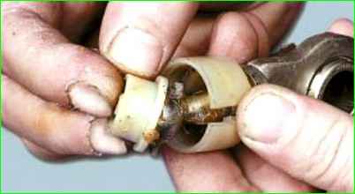
Spread the spherical washer and remove the ball joint
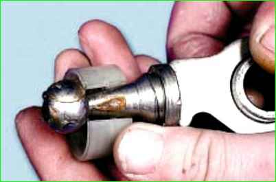
Remove the spherical washer from the spherical pin of the lever
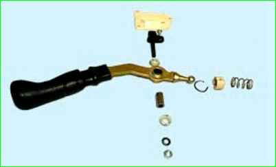
This is what the gear shift lever parts look like
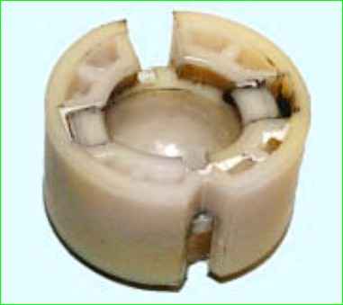
Replacing a broken or badly worn spherical washer and ball joint
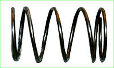
Replacing spring, if it has lost elasticity or broken
We assemble and install the lever in the reverse order, having previously lubricated the ball pin of the lever and the inner cavity of the cage.
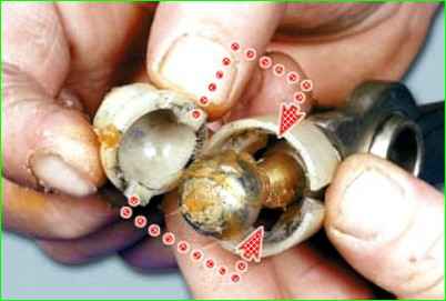
When installing the ball joint, you need to pay attention to the fact that the protrusions on it enter the grooves of the spherical washer
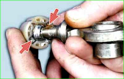
Having fixed the clip in the washer
Adjusting the gearbox control drive
Adjust the control drive after removing and installing the gearbox or if gear shifting is unclear during vehicle operation.
Install the vehicle on a lift or inspection pit
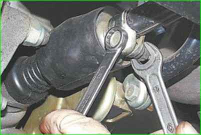
From below the vehicle, loosen and unscrew the nut by 3-5 turns tightening bolt of the clamp on the gearbox control rod
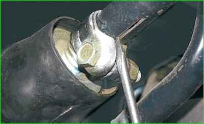
We use a screwdriver to widen the groove of the clamp at the end of the rod to ensure free movement of the rod relative to the gear selection rod, and install we put the rod in neutral position.
In the car interior, remove the gear shift lever boot from the handle, lower the boot down the lever and install the lever so that its lower (unbent) end is approximately vertical.
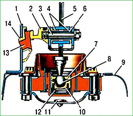
If there is a template 67.7834.9527, we set the gear shift lever as follows: with the lever cover removed, install the template in the window of lining 14 (figure) of the reverse gear lock bracket.
Insert stop 2 of the lever 5 axis into the groove of template 13 and press it against the template in the transverse direction, without causing elastic deformation of bracket 1.
Fix lever 5 in this position.
From below the car, with light movements (so as not to move the gear selection levers), we select the axial play of the rod in the rear direction and its angular play in the counterclockwise direction
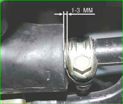
Tighten the clamp tightening bolt nut, setting the clamp at a distance of 1-3 mm from the end of the rod.


