Most electrical circuits are protected by fuses. Powerful consumers are connected via relays
All relays (except for the trunk glass heating relay), power fuses and engine management system fuses are installed in the relay and fuse box located in the engine compartment on the left, behind the battery.
The remaining fuses are located in the fuse box installed in the passenger compartment at the left end of the instrument panel.
The trunk glass heating relay is installed on the crossbar under the instrument panel.
Fuses in the engine compartment mounting block
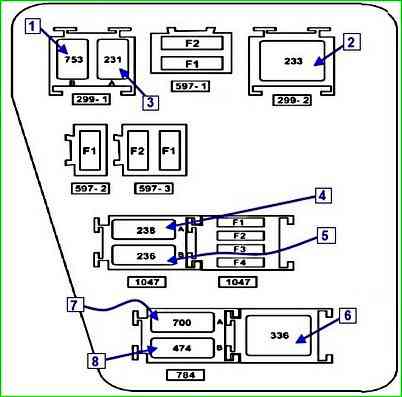
Fuse purpose (depending on equipment level)
- F1 - 30A - BP7 - Fuse: relay board power supply (784)
- F2 - 25A - BP17 - Fuse: injection system relay power supply circuits (1047)
- F3 - 5A - BP37 - Fuse: injection system relay power supply circuits (1047). Injection system ECU (120)
- F4 - 15A - BP33 - Fuse: gas supply system electromagnetic valve power supply circuits (1259)
- F1(15) - Not used
- F2(5) - Circuits: constant power supply to the engine management system ECU; windings of the main relay K5 of the engine management system
- F3(25) - Power circuits: relay K4 of the fuel pump and ignition coil; main relay K5 of the engine management system
- F4(30) - Power circuit of relay K3 of the cooling system fan (on a vehicle without air conditioning)
- F5(40) - Power circuits: relay K2 of the air conditioning; relay K3 of the low speed of the cooling system fan (on a vehicle with air conditioning); relay K1 of the high speed of the cooling system fan (on a vehicle with air conditioning)
- F6(25) and F7(50) - Circuits of the ABS control unit
- F8(60) - Circuits: power supply of the ignition switch and all consumers recorded from the switch; left steering column switch
- F9(60) - Passenger compartment fuse box power supply circuit
Engine compartment fuse box relay
- K1 - High-speed cooling fan relay (for vehicles with air conditioning). Cooling fan motor
- K2 - Air conditioning relay. Air conditioning compressor electromagnetic clutch
- K3 - Low-speed cooling fan relay (for vehicles with air conditioning) or cooling fan relay (on vehicles without air conditioning). Cooling fan motor (for vehicles with air conditioning - via resistor)
- K4 - Fuel pump and ignition coil relay. Fuel pump and ignition coil
- K5 - Main engine management system relay. Oxygen concentration sensors (heating circuit); speed sensor; fuel injectors; electromagnetic valve for purging the adsorber; relay windings K1, K3, K2; engine management system ECU
- K6 - Not used
- K7 - Fog light relay. Fog light bulbs
- K8 - Heater fan relay. Heater Fan Motor
To replace fuses or relays, disconnect the negative terminal from the battery.
To access the fuses and relays in the engine compartment, press the three latches
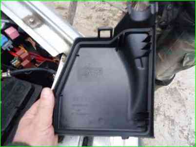
Remove the cover of the mounting block
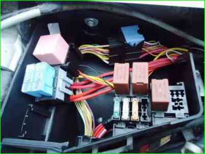
A faulty fuse can be identified by a burnt-out jumper visually or using a tester.
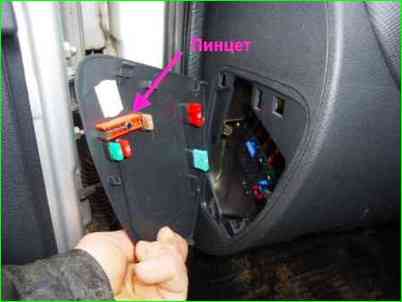
You can use atweezers, which are located on the cover of the passenger compartment unit.
A new fuse or relay should be installed only after you have found the reason for its operation. It is necessary to determine why an overload occurred in this circuit.
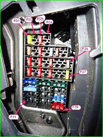
Fuses in the fuse box in the passenger compartment of the car
- F01(20) - windshield wiper; windings of the relay for heating the glass of the tailgate; switching unit
- F02(5) - power supply for the instrument cluster; windings of relay K4 of the fuel pump and ignition coils; power supply of the engine management system ECU from the ignition switch
- F03(20) - brake light bulbs
- F04(10) - turn signal bulbs; engine management system diagnostic connector; immobilizer coil; switching unit
- F09(10) - left headlight headlamps (low beam); low beam indicator in the instrument cluster
- F10(10) - right headlight headlamps (low beam)
- F11(10) - left headlight headlamps (high beam); high beam indicator in instrument cluster
- F12(10) - Right headlamp headlamp circuit (high beam)
- F13 (30) and F14 (30) - Rear and front door electric window circuits, respectively
- F15 (10) - ABS control unit circuit
- F16 (15) - Driver and front passenger seat heating circuits
- F17(15) - Horn circuit
- F18 (10) - Left headlamp side light bulbs; left rear light side light bulbs; license plate light bulbs
- F19 (10) - Right headlamp side light bulbs; right rear light side light bulbs; glove compartment light bulbs; instrument cluster and instrument panel, console and floor tunnel trim lighting; switching unit buzzer
- F20 (7.5) - Rear fog light on bulb and indicator
- F21 (5) - Exterior rear-view mirror heating element circuit
- F26 (5) - Airbag control unit circuit
- F27 (20) - Tailgate glass wiper, glass washer, reversing light
- F28 (15) - Interior and trunk light bulbs; constant power supply for audio head unit; instrument cluster
- F29 (15) - Hazard warning light switch; direction indicator switch; intermittent windscreen wiper mode; central locking control; diagnostic connector of the engine management system; switching unit
- F30 (20) - Central locking circuits; switch unit
- F31 (15) - Power circuit of the K7 fog lamp relay winding
- F32 (30) - Power circuit of the trunk glass heating relay
- F36 (30) - Power circuit of the K8 heater fan relay
- F37 (5) - Circuits of the electric drives of the outside rear-view mirrors
- F38 (10) - Cigarette lighter, power supply of the head unit of audio reproduction from the ignition switch
- F39 (10) - Windings of the K8 heater fan relay
To access and replace the fuses in the passenger compartment, remove the fuse cover, which is located on the left side of the instrument panel.
On the inside of the mounting block cover there are spare fuses 1 (rated for 5, 10, 15 and 30 A), tweezers-puller 2 for extracting fuses from the block, and a diagram of the location of the fuses is also shown.
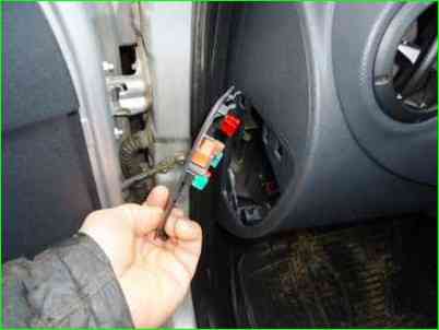
Overcoming the resistance of the cover latches, we remove it
On the cover there are spare fuses and tweezers for extracting fuses


