Removing the steering column switches for replacement, as well as when removing the steering column and instrument panel
To complete the task, you will need the following tools: Torx T20, T50 keys, a set of screwdrivers, a tester
Preparing the car. Disconnect the negative terminal of the battery.
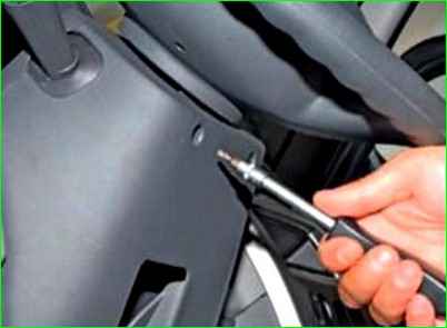
Unscrew the two bolts securing the steering column casing
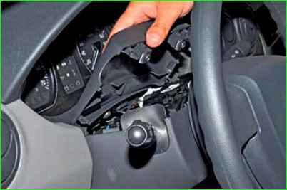
Remove the upper part of the casing
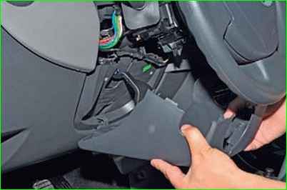
Remove the lower part of the steering column casing
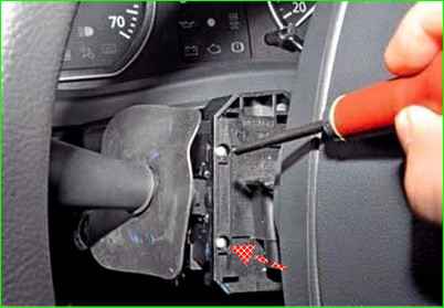
Unscrew the two screws securing the steering column switch
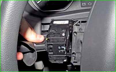
Remove the switch from the connector socket
Disconnect the wiring block from the switch
Remove the second steering column switch in the same way
After this, check the correctness of the switch contacts closure at different positions of the switch levers.
Connect the tester with the continuity function to the corresponding terminals indicated below in accordance with the figures
When when the switch lever is moved to the corresponding position - the tester should show a closed contact, otherwise the switch is faulty.
Contact closure at different positions of the switch lever for external lighting and turn signals with a horn button:
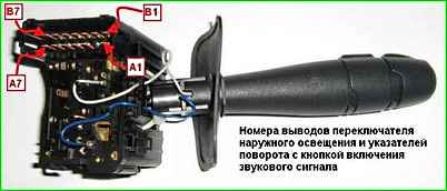
- Left turn signal A7-A6;
- Right turn signal A5-A6;
- Parking light B1-B2;
- Low/high beam switch B5-B3;
- High beam headlights B5-B3 ÷ B7-B6;
- Front fog lights A1-B2 ÷ B1-B2;
- Rear fog light A3-B2 ÷ B1-B2;
- Horn A4-B6
Contact closure at different positions of the windshield wiper and washer switch lever with the trip computer display mode switching button:
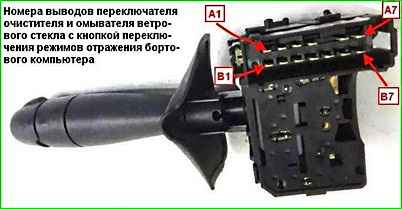
- Windshield washer pump A4-B4;
- Low wiper speed A3-A7;
- High wiper speed A2-A7;
- Intermittent wiper mode, low speed A3-A6;
- Trip computer display mode switching button A4-B7
We install the switches in the reverse order.
Removing the steering column switches together with the connector and the airbag contact ring
We prepare the car and disconnect the negative terminal battery
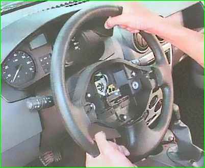
Removing the ul, as described in the article “Removing the steering wheel and steering column cover of a Lada Largus car”
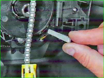
To avoid damaging the airbag contact ring current-carrying busbar, secure itwe take the ring from turning
To do this, insert a piece of thin plate into a special groove on the outer circumference of the ring (a piece from the CV joint boot clamp may work).
Before installation, do not forget to remove the retainer!
Remove the steering column cover as described above
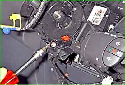
Unscrew the connector mounting clamp bolt by three or four turns
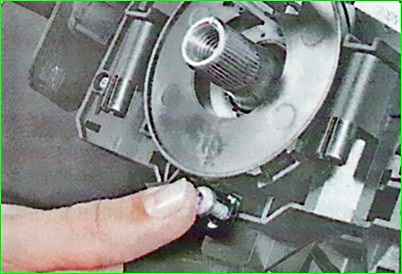
Press the bolt to loosen the clamp
Slide the connector off the steering column
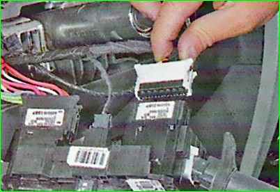
Disconnect the white connector block of wires from the steering column switches
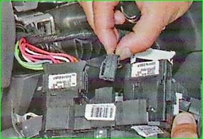
Disconnect the small black connector block of wires
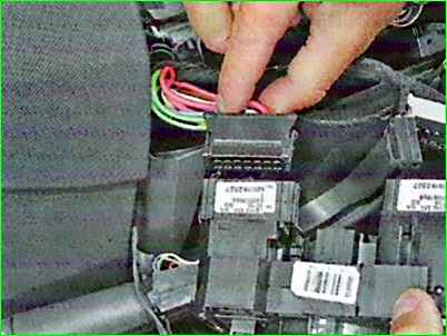
Disconnect the black wiring block and remove the connector assembly with the steering column switches and contact ring
Install the steering column switches and all removed parts in reverse order


